


Appendix A Connector Descriptions
Serial Hardware and Software for Windows A-2 ni.com
For information about setting the transceiver mode for two-wire
communication, refer to Chapter 6, Using Your Serial Hardware.Formore
information about duplex architectures, refer to Appendix B, Serial Port
Information.
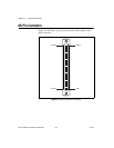
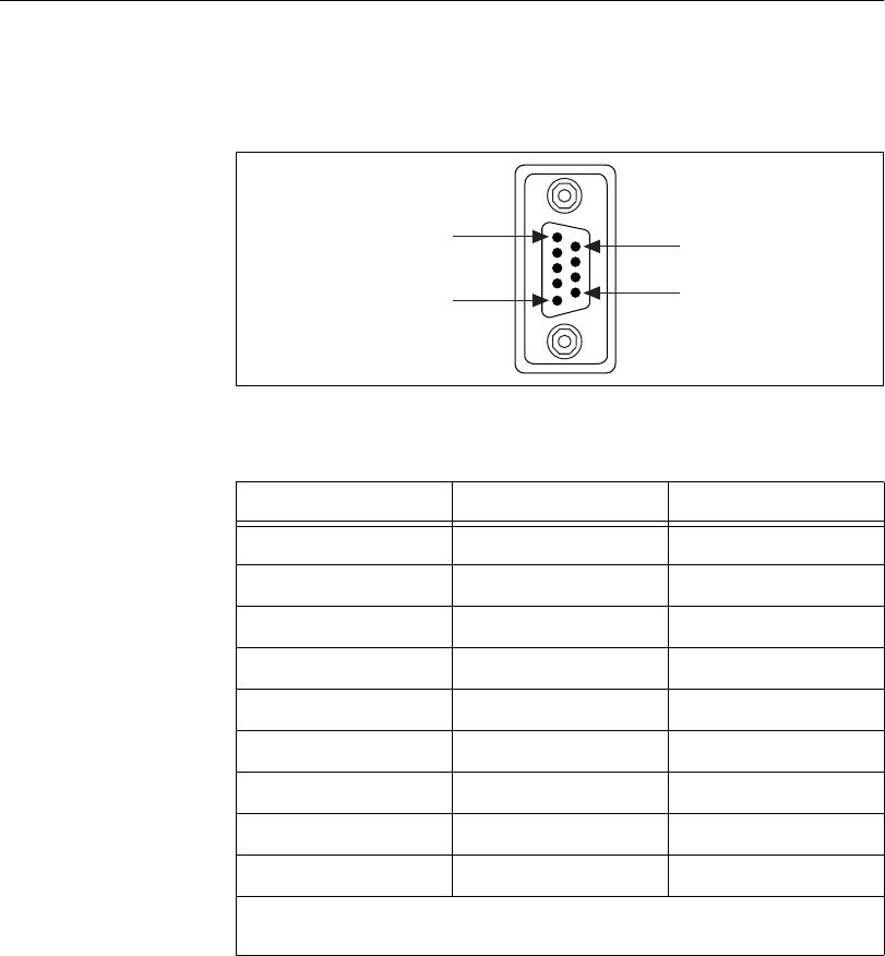
DB-9 Connector
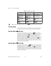
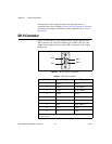
Figure A-1 and Table A-1 give the pin locations and descriptions of the
DB-9 connector, the 10-position modular jack to DB-9 cable, the cable
adapter for the eight-port board, and the DB-9 connectors to the 16-port
breakout box.
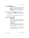
Figure A-1. DB-9 Connector Pin Locations
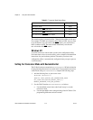
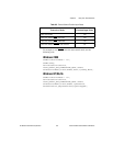
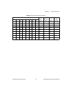
Table A-1. DB-9 Pin Descriptions
DB-9 Pin 232 Signal 485 Signal
1 DCD* GND
2 RXD CTS+ (HSI+)
3 TXD RTS+ (HSO+)
4 DTR* RXD+
5 GND RXD–
6 DSR* CTS– (HSI–)
7 RTS RTS– (HSO–)
8 CTS TXD+
9 RI* TXD–
* These signals are not supported by the isolated 232 boards or ports 9-16 of the RS-232
sixteen-port board.
PIN 1
PIN 9
PIN 5
PIN 6