


Chapter 3 I/O Information
© National Instruments Corporation 3-5 NI PXI-8184/8185 User Manual
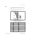
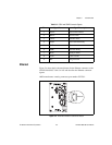
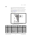
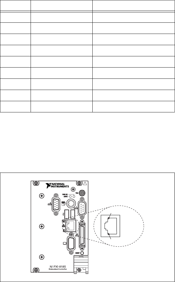
Ethernet
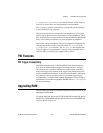
Figure 3-4 shows the location and pinouts for the Ethernet connector on the
NI PXI-8184/8185. Table 3-4 lists and describes the Ethernet connector
signals.
AMP manufactures a mating connector, part number 554739-1.
Figure 3-4. Ethernet Connector Location and Pinout
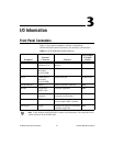
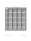
Table 3-3. COM1 and COM2 Connector Signals
Pin Signal Name Signal Description
1 DCD* Data Carrier Detect
2 RXD* Receive Data
3 TXD* Transmit Data
4 DTR* Data Terminal Ready
5 GND Ground
6 DSR* Data Set Ready
7 RTS* Ready to Send
8 CTS* Clear to Send
9 RI* Ring Indicator
Ethernet
1
8