


Chapter 3 I/O Information
NI PXI-8184/8185 User Manual 3-10 ni.com
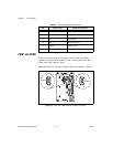
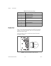
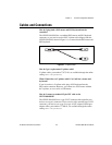
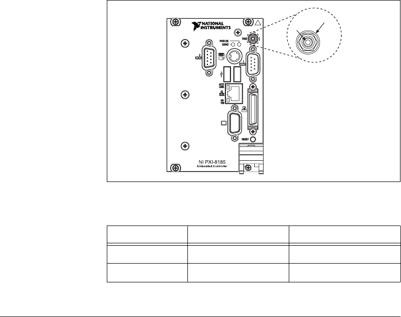
Trigger
The TRG connector is the software-controlled trigger connection for
routing PXI triggers to or from the backplane trigger bus.
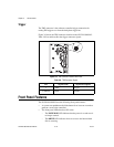
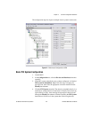
Figure 3-8 shows the TRG connector location on the NI PXI-8184/8185.
Table 3-8 lists and describes the trigger connector signals.
Figure 3-8. TRG Connector Location and Pinout
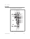
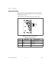
Front Panel Features
The NI PXI-8184/8185 have the following front-panel features:
• A system reset pushbutton (hold the button for at least two seconds to
generate a reset to the controller).
• Two front-panel LEDs that show PC status.
– The POWER OK LED indicates that the power is on and reset is
no longer asserted.
– The DRIVE LED indicates when an access to the internal hard
disk is occurring.
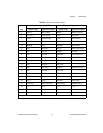
Table 3-8. TRG Connector Signals
Pin Signal Name Signal Description
1 TRIG Trigger
2 (Shield) GND Ground
1
2