


Chapter 4 Theory of Operation
SCXI-1141/1142/1143 User Manual 4-6 ni.com
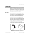
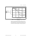
As Figure 4-2b shows, a real filter has ripple (an uneven variation in
attenuation versus frequency) in the passband, a transition region between
the passband and the stopband, and a stopband with finite attenuation and
ripple.
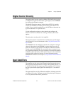
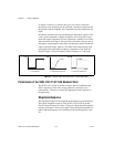
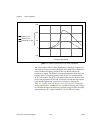
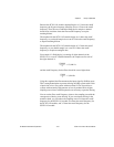
In addition, real filters have some nonlinearity in their phase response. This
causes signal components at higher frequencies to be delayed by longer
times than signal components at lower frequencies, resulting in an overall
shape distortion of the signal. You can observe this when a square wave or
step input is sent through a lowpass filter. An ideal filter simply smooths the
edges of the input signal, whereas a real filter causes some ringing in the
total signal because the higher-frequency components of the signal are
delayed. Figure 4-3 shows examples of these responses to a step input.
Figure 4-3. Real and Ideal Filter Responses to a Step Input Signal
Performance of the SCXI-1141/1142/1143 Module Filters
The SCXI-1141/1142/1143 module is elliptic, Bessel, and Butterworth
filters, respectively. Each filter design optimizes a particular set of
characteristics. Therefore, selecting the appropriate module depends on
the application.
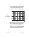
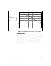
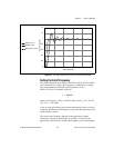
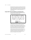
Magnitude Response
The magnitude response is the amplitude of the output at a given frequency.
The typical magnitude response of the SCXI-1141/1142/1143 module
filters is shown in Figures 4-4 and 4-5. Figure 4-4 shows the full magnitude
response and Figure 4-5 shows the ripple in the passband. Both graphs are
plotted with the frequency axis normalized to the cutoff frequency value
of 1.
b. Ideal Filter Responsea. Input Signal
VoltsVolts
Time Time
c. Real Filter Response
Volts
Time