


Navini Networks, Inc. Ripwave MX Modem User Guide
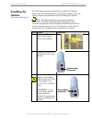
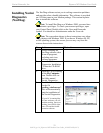
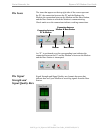
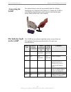
The Icons
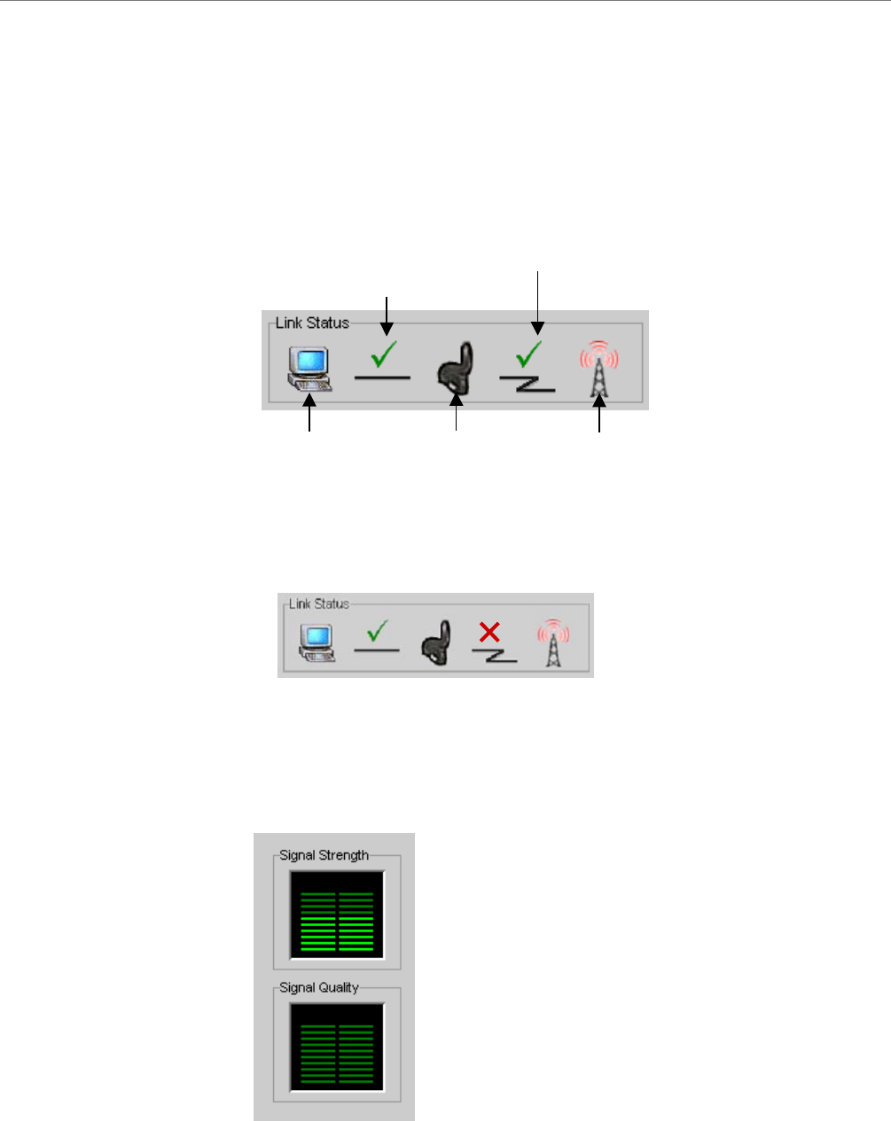
The Signal
trength and
ignal Quality Bars
ppear on the top r e screen represent
PC the PC and the Modem, the
Modem the Modem and the Base Station,
and the Base Station to which the Modem is communicating.
Check ections indicate working connections.
An “X” is positioned over the corresponding icon indicates the
connection between the PC and the Modem or between the Modem
and the Base Station is interrupted.
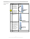
Signal Strength and Signal Quality are dynamic bar areas that
indicate how well your Modem is receiving signals from the Base
Station
S
S
The icons that a ight side of th
the , the connection between
, the connection between
marks over the conn
.
P
Conne
P
Base Station
Connection between
m & Base Station
C
Modem
ction between
C & Modem
Mode
P
Conne
P
Base Station
Connection between
m & Base Station
C
Modem
ction between
C & Modem
Mode
19
060210_pv1.6_Ripwave-MX Modem User Guide_40-00382-00b(4.4.2)