


General Description 2-9
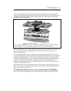
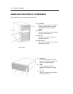
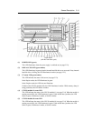
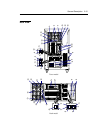
(12) CPU/IO module #0
This is a module with a set of CPU (processor), memory (DIMM), PCI board, and cooling
fan unit (see page 2-18).
(13) CPU/IO module #1
This is a module with a set of CPU (processor), memory (DIMM), PCI board and cooling fan
(see page 2-18).
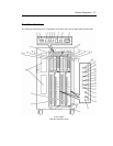
(14) Module POWER switch
This switch is used to control power supply to a module. The switch is pressed when
removing a failed module.
(15) Module POWER LED
See page 2-25.
(16) Module FAULT LED
See page 2-25.
(17) Processor error LED
See page 2-25.
(18) I/O error LED
See page 2-25.
(19) Memory group 3 error LED
See page 2-25.
(20) Fan 2 error LED
See page 2-25.
(21) Fan 1 error LED
See page 2-25.
(22) Memory group 2 error LED
See page 2-25.
(23) Voltage error LED
See page 2-26.
(24) Memory group 1 error LED
See page 2-25.
(25) HCS2 error LED
See page 2-26.
(26) Power supply unit error LED
See page 2-26.