


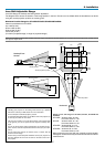
2-9
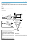
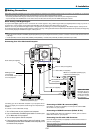
To connect SCART output (RGB)
Before connections: An exclusive SCART adapter (ADP-SC1) and a
commercially available SCART cable are required for this connection.
NOTE:
• Audio signal is not available for this connection.
• The RGB 1 IN connector does not support Plug & Play.
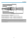
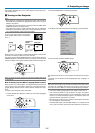
USB A USB BPC CARD
PC CONTROL
IN
IN
1
2
OUT
OUT
SC TRIGGER REMOTE 2
REMOTE 1
LAN
AC IN
AUDIO
AUDIO
AUDIO OUT
R
R/Cr
G/Y
B/Cb
V
H/
HV
R
L/MONO
R
L/MONO
R
L/MONO
L/MONO
SLOT 1 SLOT 2
DVI
RGB OUT
RGB 1
RGB 2
VIDEOS-VIDEO
RGB 2
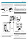
Video equipment
such as DVD player
Projector
ADP-SC1
Commercially available
SCART cable
Female
1. Turn off the power to the projector and your video equipment.
2. Use the NEC ADP-SC1 SCART adapter and a commercially
available SCART cable to connect the RGB 2 input of your
projector and a SCART output (RGB) of your video equipment.
3. Turn on the power to the projector and your video equipment.
4. Use the RGB 2 button on the remote control to select the RGB
2 input.
5. Press the MENU button on the remote control to display the
menu.
6. From the Advanced menu, select [Projector Options]
→
[Setup]
→
[Page 3]
→
[Signal Select RGB2]
→
[Scart].
SCART is a standard European audio-visual connector for TVs,
VCRs and DVD players. It is also referred to as Euro-connec-
tor.
NOTE: The ADP-SC1 SCART adapter is obtainable from your NEC dealer in Europe.
Contact your NEC dealer in Europe for more information.
To RGB 2 IN
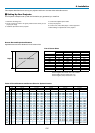
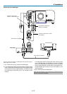
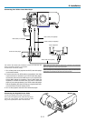
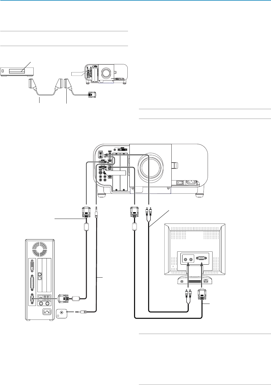
Connecting an External Monitor
You can connect a separate, external monitor to your projector to simulta-
neously view on a monitor the RGB analog image you're projecting. To do
so:
1. Turn off the power to your projector, monitor and computer.
2. Use a 15-pin cable to connect your monitor to the RGB OUT
(Mini D-Sub 15 pin) connector on your projector.
3. Turn on the projector, monitor and the computer.
NOTE:
• The RGB OUT connector outputs RGB signal during idle mode (See page 8-15).
When the projector goes into idle mode, the image on an external monitor dis-
appears for a moment. Note that the RGB OUT connector will not output RGB
signal during Standby mode.
• When the projector is in the Idle mode, the image may not be correctly dis-
played while the cooling fans are running immediately after turning on or off the
power. Note that the RGB OUT connector will not output RGB signal during
Standby mode.
• Daisy chain connection is not possible.
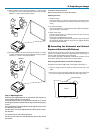
USB A USB B PC CARD
PC CONTROL
IN
IN
OUT
OUT
SC TRIGGER REMOTE 2
REMOTE 1
LAN
AC IN
AUDIO
AUDIO
AUDIO OUT
R
R/Cr
G/Y
B/Cb
V
H/
HV
R
L/MONO
R
L/MONO
R
L/MONO
L/MONO
SLOT 1 SLOT 2
DVI
RGB OUT
RGB 1
RGB 2
VIDEO S-VIDEO
PHONE
RGB OUT
LINE IN
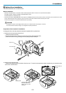
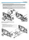
2. Installation
RGB signal cable
(not supplied)
To mini D-Sub 15-pin connec-
tor on the projector.
Audio cable
(not supplied)
Audio cable
(not supplied)
RGB signal cable
(not supplied)
To mini D-Sub 15-pin connec-
tor on the projector.