


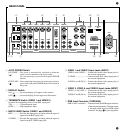
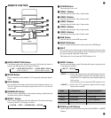

8 MONITOR Output Jack (OUTPUT)
MONITOR (BNC) ........... Outputs the signals of the equipment con-
nected to VIDEO 1 through 5.
S-VIDEO.......................... Outputs an S video signal, (derived from
the signal of the equipment connected to
VIDEO 1 or VIDEO 2), which has been
divided to a luminance signal (Y) and a
chrominance signal (C).
AUDIO L and R (RCA) ... Outputs the signal of the equipment con-
nected to VIDEO input 1 through 5 and the
AUDIO L and R associated with the RGB
input connector.
The selected video signal is output when
RGB input has been selected and MONI-
TOR button is switched on.
9 RGB Output Connector (OUTPUT)
RGB (BNC)...................... Connected to the RGB input jacks of a
monitor or projector having a 31.5 kHz
horizontal scanning function.
HORIZONTAL (BNC) .... Connected to the HORIZONTAL input
jack of a monitor or projector having a 31.5
kHz horizontal scanning function.
VERTICAL (BNC) .......... Connected to the VERTICAL input jack of
a monitor or projector having a 31.5 kHz
horizontal scanning function.
H/V (BNC) ....................... Connected to the H/V input jack of a moni-
tor or projector having a 31.5 kHz horizon-
tal scanning function.
AUDIO L and R (RCA) ... Connected to the audio input jacks of RGB
equipment.
0 HV POL. Switch
Selects the polarity of the horizontal and vertical output signals.
H .............. Horizontal
V .............. Vertical
Hi............. Active high
Lo ............ Active low
A PC-CONTROL SW (Switch)
Selects the communications standard of the PC-CONTROL connector.
422 ........... RS-422 standard
232 ........... RS-232C standard
B AC IN Receptacle
Used to connect the supplied power cord.
C PC-CONTROL Connector (15-pin connector)
Connect to a personal computer or other control equipment.
0
A
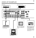
D EXTERNAL CONTROL Connector
Connections are made to this connector when controlling this unit by
external control.
(See the “External Control Mode” section.)
NOTE :
• Use a signal conforming to the standard TV signal when connecting
an input source.
• Using poor quality video tape may cause distortion on the picture.
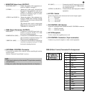
Pin No.
1
2
3
4
5
6
7
8
9
10
11
12
13
14
15
Signal to be connected
Red input
Green input
Blue input
GND
GND
Red GND
Green GND
Blue GND
Open
Sync GND
GND
Open
H-Sync
V-Sync
Open
54321
10 9 8 7 6
15 14 13 12 11
RGB (D-Sub 15 mini) Connector Pin Assignment