


CHAPTER 5 ND-91649(E)
Page 42
SPECIFICATIONS
CHAPTER 5 SPECIFICATIONS
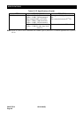
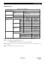
System Capacity
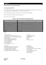
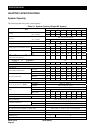
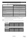
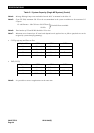
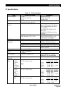
The following table shows the system capacity.
Table 5-1 System Capacity (Single MP System)
System Capacity Note 1, 2
Item
1PIM 2PIM 3PIM 4PIM 5PIM 6PIM 7PIM 8PIM
64 128 192 256 320 384 448 512
(No. of Ports)
LT Card
(No. of Cards)
12 24 36 48 60 72 84 96
Max. 256 ports per system
(No. of Ports)
AP Card
(No. of Cards)
12 24
Total Number of Lines (Analog Single Line Tel. + D
term
) 64 128 192 256 320 384 448 512
IP PAD Note 3 (No. of Channel)
64 128 192 256
Standard 64 128 192 256 320 384 448 512
Analog Single Line Telephone (Lines)
Long Note 4 44 92 140 188 236 284 332 380
Standard 64 128 192 256 320 384 448 512
D
term
Long 22 46 70 94 118 142 166 190
D
term
IP/ D
term
IP INASET/ D
term
SP20/ D
term
SP30
(Peer-to-Peer Connection)
448 384 320 256 192 128 64 0
D
term
PS (Asia) / D
term
PS (LA) Note 5 256
Cell Station (CS) / Zone Transceiver (ZT) Note 6
16 32 48 64 80 96 112 128
IP-BS (PHS) Note6
112 Note 7
ISDN Station
16 32 48 64 80 96 112 128
Loop Start
64 128 192 256 256 256 256 256
Central Office Trunk (Lines)
DID w/4DIT 48 96 144 192 240 256 256 256
4LDT 48 96 144 192 240 256 256 256
2W E&M 24 48 72 96 120 144 168 192
Tie Line Trunk (Lines)
4W E&M 24 48 72 96 140 144 168 192
CCIS Trunk (Peer-to-Peer Connection) Max. 127
1.5M-AMI DTI : 10, CCIS : 8
DTI/CCIS Digital Link Note 1
2M-AMI Max. 8 Links per system
1.5M/2M-AMI (PRT) 8
2BRT (card) 12 24
ISDN
4BRT (card) 6 12 18 24 24 24 24 24
IP Trunk Note 7 1 2 3 4 5 6 7 8
PFT Connections 8PFT 8 16 24 32 40 48 56 64
3-Party Conference Max. 16 conference groups per system
6-Party Max. 4 conference groups per system
6-/10-Party Conference
10-Party Max. 2 conference groups per system
32-Party Conference Max. 8 conference groups per system
M13 (Splitter Card for HomePNA / VDSL DPC) PIM 0: Max. 11, PIM 1-7: Max. 12 cards per PIM
In-skin Router Max. 8 cards per PIM
DTMF Sender Max. 32 circuits per system
DTMF Receiver 16 32
SN716 Desk Console 8