


ND-91649(E)
ISSUE 3
LIST OF ILLUSTRATIONS ND-91649(E)
Page ii
LIST OF ILLUSTRATIONS
Figure Title Page
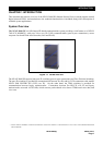
Figure 1-1 NEAX 2000 IPS...................................................................................................................................1
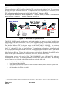
Figure 1-2 NEAX 2000 IPS System Overview....................................................................................................2
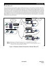
Figure 1-3 Example of Network Configuration of Remote PIM over IP..........................................................3
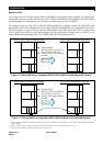
Figure 1-4 Retrofit MP/FP for Upgrading NEAX 7400 ICS M100 to IPS (Single MP System)........................4
Figure 1-5 Retrofit MP/FP for Upgrading NEAX 7400 ICS M100 to IPS (Dual MP System)...........................4
Figure 1-6 Trunking Diagram of NEAX 2000 IPS ..............................................................................................9
Figure 2-1 Module Configuration of NEAX 2000 IPS......................................................................................10
Figure 2-2 Face Layout of NEAX 2000 IPS ......................................................................................................11
Figure 2-3 Wall-mounting of PIM......................................................................................................................12
Figure 2-4 19-inch Rack-mounting...................................................................................................................13
Figure 3-1 DESK Console .................................................................................................................................18
Figure 3-2 D
term
2 (White)...................................................................................................................................22
Figure 3-3 D
term
8 (White)...................................................................................................................................22
Figure 3-4 D
term
8D (White) ................................................................................................................................22
Figure 3-5 D
term
16D (White)..............................................................................................................................23
Figure 3-6 D
term
32D (White)..............................................................................................................................23
Figure 3-7 DSS Console (Black).......................................................................................................................23
Figure 3-8 D
term
16LD (Black)............................................................................................................................24
Figure 3-9 Analog Port Adapter (APR) ............................................................................................................24
Figure 3-10 Ancillary Device Adapter (ADA)...................................................................................................24
Figure 3-11 Computer Telephony Adapter (CTA)...........................................................................................25
Figure 3-12 IP Adapter (IPW) ............................................................................................................................25
Figure 3-13 System Configuration of Wireless Communications ................................................................29
Figure 3-14 Cell Station (CS), IP Base Station (IP-BS) and PHS Personal Station (PS).............................33
Figure 3-15 Zone Transceiver (ZT) and PCS Personal Station (PS).............................................................36
Figure 3-16 SP30 Screen...................................................................................................................................37