


E – 11
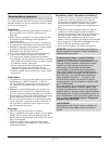
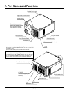
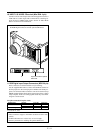
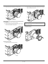
Push the left side of the panel to open the compartment for
the RGB Digital connectors and the optional SDI board.
Space to install the optional
SDI board.
OUTPUT OUTPUT
RGB
DIGITAL
INPUT9 INPUT 0
SDI
11
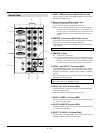
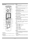
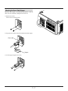
10 INPUT 8 S-VIDEO 2Terminal (Mini DIN 4 pin)
Connect to the S-video output of the external equipment such as a
VCR with an S-video output. This terminal allows switching be-
tween S2 and S1 VIDEO input modes. See the "S-Video Mode
Select" section for more information.
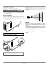
11 RGB Digital Input/Output Connectors (MDR 20 pin)
These connectors are used for double or triple stacking.
Use the supplied DFP cable to connect the OUTPUT terminal of
the first projector to the second projector's INPUT until all the pro-
jectors are connected. These connectors can also be used to accept
TMDS standard (Pannel Link) digital signal output from a digital
ready computer. In this case some graphics cards may cause flick-
ering noise on the screen.
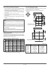
List of Recommended Graphics Cards
Manufacturer Product Card I/F Connector
I-O Data Devices, Inc. GA-SS21P8/PCI PCI DFP 20P
GA-SM02P2/CB PCMCIA DFP 20P
ATI Technologies, Inc. Expert LCD AGP DFP 20P
As of October 31, 1999
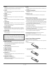
NOTE:
* These connectors support a maximum resolution of 1024ן768
(XGA).
* A DFP cable must be 5 m (16.4 feet) or less in length.
* Contact your dealer for installing the optional SDI board.