


NB712 / NB714 User Guide 113
YML829 Rev1
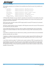
Straight and crossover cable configuration
There are two types of the wiring: Straight-Through Cables and Crossover Cables. Category 5 UTP/STP cable has
eight wires inside the sheath. The wires form four pairs. Straight-Through Cables has same pinouts at both ends
while Crossover Cables has a different pin arrangement at each end.
In a straight-through cable, wires 1,2,3,4,5,6,7 and 8 at one end of the cable are still wires 1~8 at the other end.
In a crossover cable, the wires of 1,2,3,6 are reversed so that wire 1 become 3 at the other end of the cable, 2
becomes 6, and so forth.
To determine which wire is wire 1, hold the RJ-45 cable tip with the spring clip facing towards the ground and the
end pointing away from you. The copper wires exposed upwards to your view. The first wire on the far left is wire
1. You can also refer to the illustrations and charts of the internal wiring on the following page.
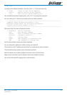
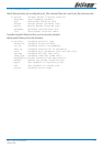
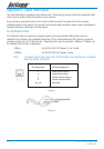
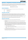
Straight-Through Cabling
Figure 3
Wire Becomes
1 1
2 2
3 3
6 6
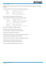
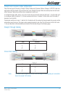
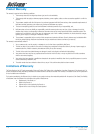
Cross-Over Cabling
Figure 4
Wire Becomes
1 3
2 6
3 1
6 2
Note: To prevent loss of signal, make sure that the length of any twisted-pair connection
does not exceed 100 metres.