


CHAPTER 2: PHYSICAL DESCRIPTION
This chapter describes the hardware features of the NETGEAR Model FSM7352S Layer 3 Managed
Stackable Fast Ethernet Switch. Topics include:
Front and back panels
48 10/100 Mbps and 4 10/100/1000 Mbps auto-sensing RJ-45 ports
SFP module bay
LED descriptions
Console port
Front and Back Panels
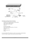
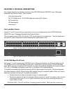
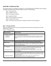
Figures 2-1 and 2-2 show the key components on the front and back panels of the NETGEAR Model
FSM7352S Layer 3 Managed Stackable Fast Ethernet Switch
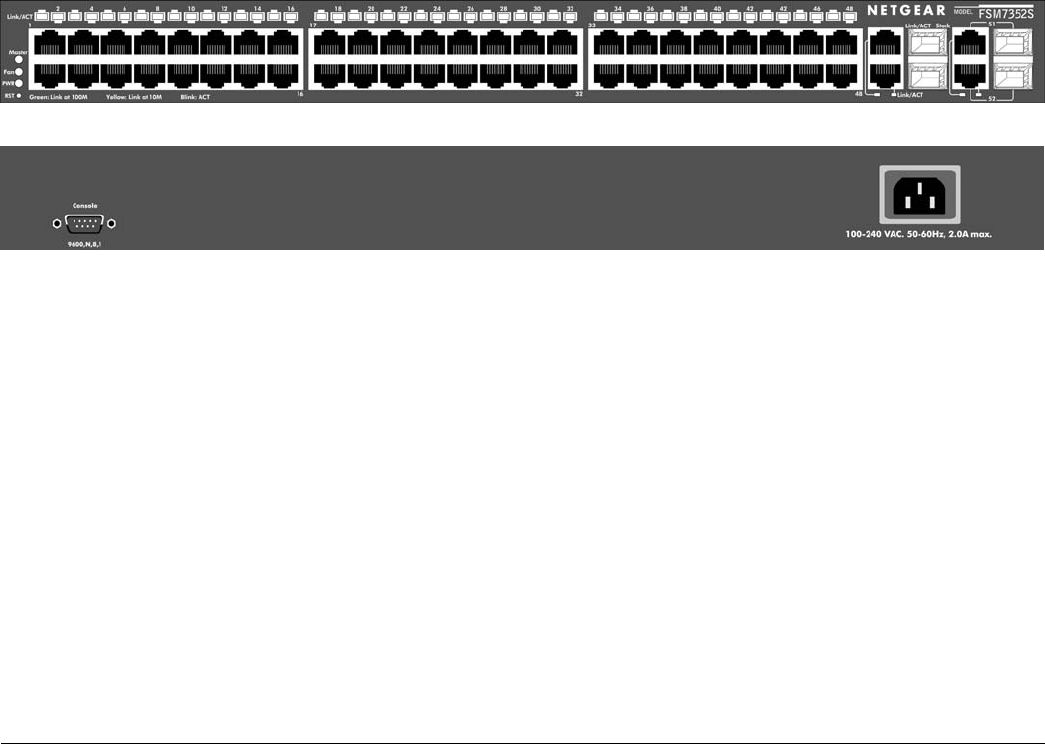
The front panel contains LEDs, RJ-45 jacks, SFP module bays, and a console port. The back panel has a
standard AC power receptacle for accommodating the supplied power cord.
Figure 2-1. Front Panel of the FSM7352S Layer 3 Managed Stackable Fast Ethernet Switch
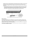
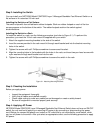
Figure 2-2. Back Panel of the FSM7352S Layer 3 Managed Stackable Fast Ethernet Switch
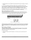
10/100/1000 Mbps RJ-45 Ports
As Figures 2-1 and 2-3 shows, the FSM7352S Layer 3 Managed Stackable Fast Ethernet Switch has 48
10/100 Mbps and 4 10/100/1000 Mbps RJ-45 ports. These 4 ports are auto-sensing 10/100/1000 Mbps
ports: When you insert a cable into an RJ-45 port, the switch automatically ascertains the maximum speed
(10, 100, or 1000 Mbps) and duplex mode (half- or full-duplex) of the attached device.
To simplify the procedure for attaching devices, all RJ-45 ports support Auto Uplink. This technology lets
you attach devices to the RJ-45 ports using either straight-through or crossover cables. When you insert a
cable into the switch’s RJ-45 port, the switch automatically:
• Senses whether the cable is a straight-through or crossover cable.
• Determines whether the link to the attached device requires a “normal” connection (such as when
connecting the port to a PC) or an “uplink” connection (such as when connecting the port to a
router, switch, or hub).
[SPECIAL NOTE: Ports 27 and 28 are in stacking mode by default. While you may connect and
Page 9 of 24