


2-12 User’s Reference Guide
You will need:
■
A Windows 95 or 98–based PC or a Macintosh computer with Ethernet connectivity for configuring the
Netopia. This may be built-in Ethernet or an add-on card, with TCP/IP installed and configured. See
“Sharing the Connection” on page 3-15.
■
A G.shdsl wall outlet wired for a connection to a Local Exchange Carrier (LEC) who supports Symmetric
Digital Subscriber Line connections.
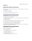
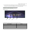
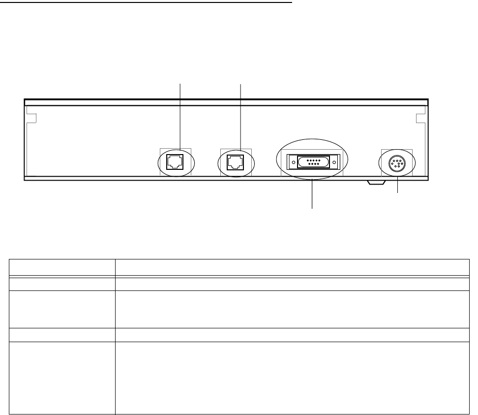
Identify the connectors and attach the cables
Identify the connectors and switches on the back panel and attach the necessary Netopia Router cables.
The figure below displays the back of the Netopia 4553 Router.
Netopia back panel
.
1. Connect the mini-DIN8 connector from the power adapter to the power port, and plug the other end into an
electrical outlet.
2. Connect one end of the Category 5 cable to the DSL port, and the other end to your DSL wall outlet.
Port Description
Power port A mini-DIN8 power adapter cable connection.
Console port A DB-9 console port for a direct serial connection to the console screens. You
can use this if you are an experienced user. See “Connecting a console cable to
your router” on page 5-27.
DSL port An RJ-48 jack labeled DSL for your G.shdsl connection.
Ethernet port An RJ-45 10/100Base-T Ethernet jack. You will use this to configure the
Netopia. For a new installation, use the Ethernet connection. Alternatively, you
can use the console connection to run console-based management using a
direct serial connection. You can either connect your computer directly the
Ethernet port using a crossover cable, or connect both your computer and the
Netopia to an existing Ethernet hub on your LAN.
Console Power
Ethernet port
Console port
Power port
G.shdsl port
DSL
10/100
Ethernet