


The users must consider the following cable requirements prior to connections:
- Cables must be of a Category 5 UTP or Category 1 STP or equivalent cable
type for a Fast Ethernet network. Such cables feature RJ-45 plugs at both ends
and through wiring.
- In a Fast Ethernet network, cable lengths must not exceed 100 meters (328
feet) between network end nodes and the switch.
- All end nodes connected to a Fast Ethernet switch must be equipped with Fast
Ethernet adapters complying the IEEE802.3u standard.
- Cables should be kept as far as possible from any electrical source, motor or
fluorescent light.
When uplinking two switches together, be certain to free both FES-1800 switch-
es' port 8. Plug one end of the uplink cable into the first switch's port 8, then plug in
other end of the cable to the other FES-1800 switch port 8, which must be switch to
the X position before you connect the cable.
To uplink the switch, users should be aware of the following requirements:
- The cable used to uplink both switches must be a Category 5 UTP, Category 1
STP or equivalent.
- The maximum length of the uplink cable must not exceed one hundred meters.
The switch can now be connected to the power cord.
Checking Port Status
Once the switch is connected to the power cord, the power indicator will blink
steadily. The switch will then automatically test each port connection. Users need
to turn on the end node to test port connections. If it is off, the port will indicate a
connection failure. All ports connected to a powered on end node should indicate a
light link/activity and full duplex/collision.
If the end node is on but the test fails, the users should check and verify the
cable connection. If both are correctly set up, it is recommended to contact the
dealer.
If a port, indicator or any other part of the switch fails to work, users must con-
tact the dealer immediately.
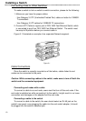
Installing a Switch
11