


A collision occurs as two end nodes are sending data simultaneously on the
network. Collisions are frequent in a Fast Ethernet network. When a collision
occurs, the two end nodes stop data transmission but backs up again later on.
However, excessive collision may indicate a sign of:
- Network overload
- Device malfunctions
- Cabling problem
Troubleshooting
The different LED’s displayed on the switch's front panel help users manage
their networks. Here is a list of common problems to help users diagnose whether
their network difficulties are related to the switch or to the external factors.
The link users need to troubleshoot the following should the front panel link of
LED does not flash:
- Check to see if the connected device is on. Check the quality of the adapter.
- Length limits for a connection between an end node and a switch can not
exceed 100 meters.
- Cable for the connection. Straight-through cables operate as to interconnect a
switch to another switch (via an uplink port), a station or a server. Cross-wired
cables, on the other hand, are to connect end nodes to another end node.
The use of crossover cable could result in connection problems.
- Quality of the cable. Check the defectiveness of the cable.
- Check the plugs at both ends of the cable. A loose plug can result in a false
connection.
If all of the above are checked and verified, the malfunction might be related to
the switch itself. In this case, the switch should be sent back to the retailer for a
complete hardware troubleshooting. If the connection cable or the power outlet is
defective, replace the product. Change the switch location if the power outlet can-
not be replaced.
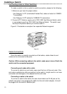
Problems can also be prevented by:
- Leaving a free space (10cm at least) in the switch's lateral fans.
- Keeping the switch away from any electromagnetic interference, lights
sources, and direct sunlight.
- Making sure that all cables do not exceed the recommended maximum length
of 100 meters.
- Checking the quality of the cables and outlets connected the switch to end
nodes and to the wall adapter.
Network Management
13