


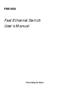


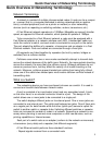

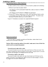

Front panel
FES-1800
Figure 1-1
The switch's front panel displays features LED (light emitting diode) indicators.
(See Figure 1-1.)
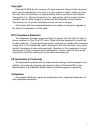
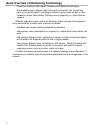
Rear panel
FES-1800
Figure 1-2
The rear panel of the switch contains the power socket and Ethernet cable con-
nectors. Its cable connectors are of RJ-45 type. RJ-45 stands for Recommended
Jack No. 45, an Electronic Industries Association (EIA) designation. Each jack
serves to connect a cable to the switch.
LED indicators allow users to check the port status and network traffic at a
glance. Exhaustive LEDs displayed on the switch allow easy network management.
The power socket accepts DC power of 5V. (See Figure 1-2)
2
General Features of a Switch