


Quick installation
This quick installation guide is provided to help the user to set up the switch in a
short time. However, it is recommended that users read through this manual before
trying installing the hardware.
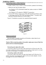
After unpacking the switch, a suitable location must be found for it. Because this
switch occupies a central location in the network, it is important to find a stable hori-
zontal surface which is clear of electromagnetic interference and equipped with a
power outlet.
Neither the switch nor any device should be powered on while installing network
components.
Now the user needs to connect all devices that will directly interface with the
new switch and with Category 5 UTP, Category 1 STP or equivalent cables. It is bet-
ter to start from the highest-numbered jack. Fast Ethernet Adapters is highly recom-
mended for all devices connecting to a Fast Ethernet Switch. The maximum cable
length between any end node in the network and the switch is 100 meters (328 feet)
for Fast Ethernet switch.
To uplink two switches together, connect both devices with a Category 5 UTP or
Category 1 STP cable at maximum length of 100 meters. When uplinking, the con-
nection can be made in port 8 via the switch on the rear panel to setup the position
to X.
All the connections have to be checked and the correct location of cables should
be verified. The switch and the connected devices can now be powered on. The
switch will indicate all port connections by blinking the correspondent port indicators.
II