


Chapter 13: VSM-6804 Digital Composite Video Signal Monitor Module Installation
112 6800/7000 Series - Distribution and Routing Products Installation and Operation Manual
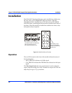
Installation
The VSM-6804 can be installed into a FR-680X Series mounting frame, a
FR-7001 series mounting frame or a FR-7000MB MIX BOX frame. A
matching back module is required when installed into the FR-7001 or
MIX BOX frames.
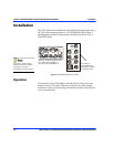
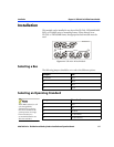
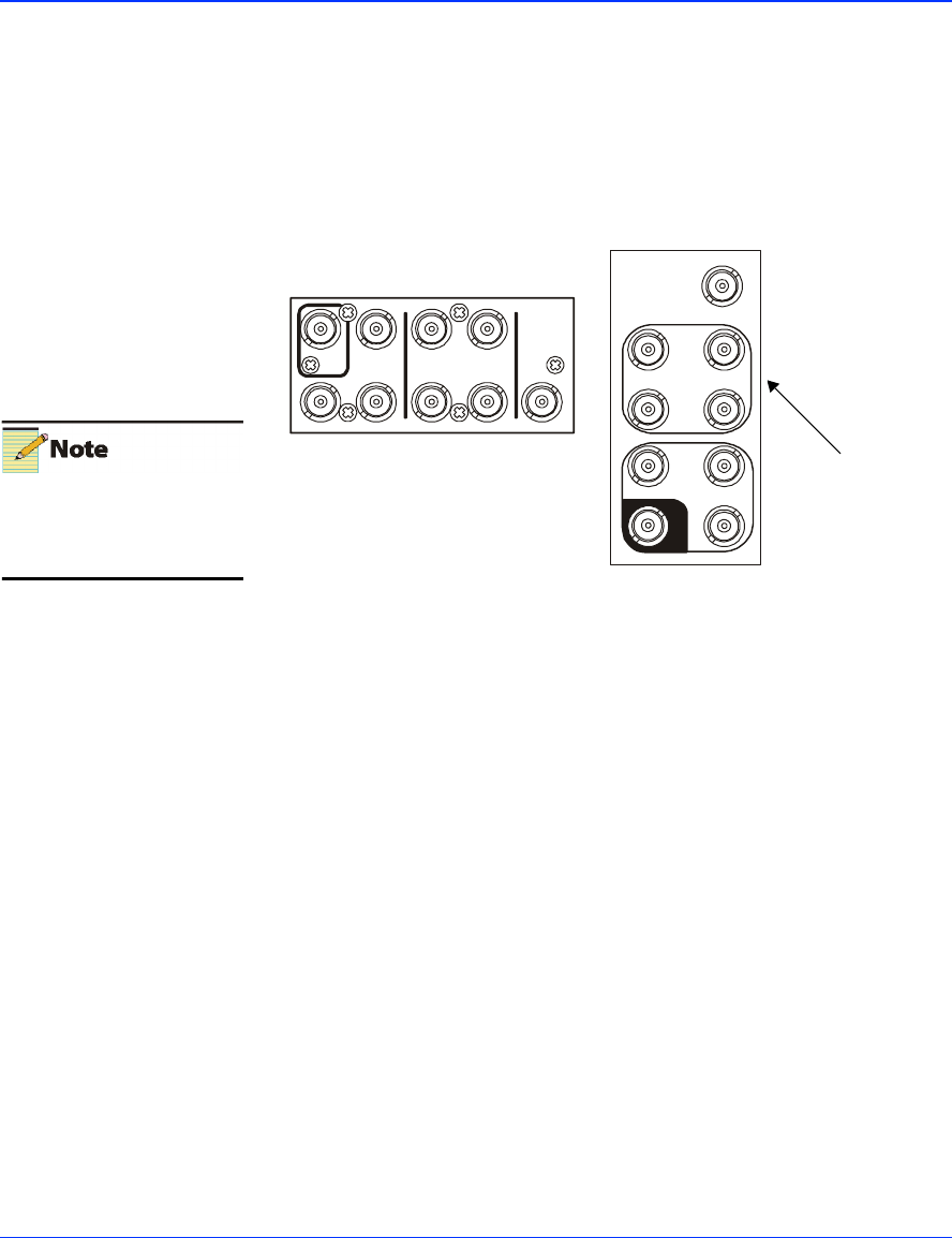
Figure 13-3. Back Module and Overlay
Operation
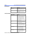
The operation of the VSM-6804 is controlled by SW2 dip switch and
jumpers J1and J2. The three LEDs located at the front of the module
indicate the status of the incoming data and line standard (forced by the
user or autodetected).
There are no frame loading
limitations since the module
consumes 3.32 W only.
Terminate any unused outputs.
V
SM-6804-M
CFID
2
13
4
31
2
SERIAL
OUTPUTS
PAL/NTSC
OUTPUTS
4:2:2
SERIAL
INPUT
3
1
4
2
SERIAL OUTPUT
4:2:2
SERIAL
INPUT
VSM-6804
7
C
F
I
D
3
12
PAL/NTSC OUTPUT
This overlay is
required when the
VSM-6804 is installed
in a FR-680x frame.
This back module is required when
the VSM-6804 is installed in a
FR-7001 or FR-7000MB frame.