Chapter 4: USM-6800 PAL/NTSC Monitoring Encoder Module Controls and Indicators
38 6800/7000 Series - Distribution and Routing Products Installation and Operation Manual
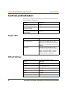
Controls and Indicators
The controls and indicators described in the tables below are located at
the front edge of the module.
Status LEDs
Default Settings
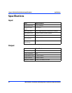
The USM-6800 is shipped with the following default settings:
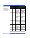
Switch Function
16-position rotary switch Selector
3-position up/down
momentary switch
Adjuster
Gain and frequency multi-turn
potentiometer
Adjuster
LEDs Function
625 Auto 525 LED When this Green Auto LED is on, this
indicates the detected standard. When the
Auto LED is off, this indicates a forced line
standard.
Error LED This Red LED indicates: there is loss of
video, the forced line standard is different
than the detected standard, or there is a
missing or mispositioned EAV-timing
reference signal in the digital data.
LEDs Function
Standard Set to Auto
Output Set to Component YUV
V Blanking Set to Pass
Setup Set to On
Burst Set to On
Chroma Set to On


