


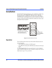

6800/7000 Series - Distribution and Routing Products Installation and Operation Manual 113
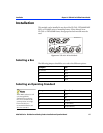
Installation Chapter 13: VSM-6804 Digital Composite Video Signal Monitor Module
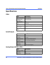
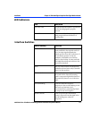
LED Indicators
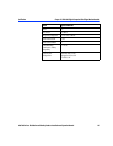
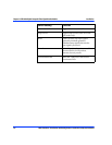
Interface Switches
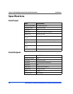
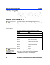
LED Indication
525 or 625 LED On indicates that the module is operational
and the incoming signal is properly
detected.
Error LED Steady On and Black Burst test signal at the
analog output indicate the absence of
incoming data.
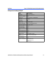
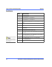
Switch Setting Function
Standard Select In the Man position the user can force the
output standard to the required mode (in
case of an input signal mismatch the
module gives the Error LED indication). If
the user always operates in only one
standard it is advisable to use the Man
mode for faster lockup. In Auto mode the
VSM-6804 determines and switches to the
detected line standard.
Force This is to select between 525 and 625 line
standard modes and active only if Standard
Select is in Man position.
525 Standard This is to select between output standards
NTSC and PALM. Since the incoming
signal is component digital this selection is
always made by the user even in the Auto
mode.
Vertical Blanking In the Pass mode the encoder is
transparent in the vertical blanking. In the
Blnk mode any luminance and
chrominance data is substituted by black.
(no setup in case of 525 signals.)
Vblank Chroma In the Off position the chrominance
content is removed from the signal in the
vertical banking area, otherwise
transparent.