


Chapter 2: DNH-6800 DigiNet Hub Module User Interface
20 6800/7000 Series - Distribution and Routing Products Installation and Opertion Manual
User Interface
Indicators and Controls
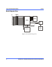
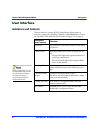
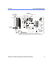
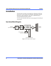
The user interface consists of LEDs that indicate various states or
activities, a jumper for disabling Channel 0, and a Reset button. These
are described in the table below and shown in Figure 2-5 on page 21.
When a signal collision occurs,
the DNH-6800 briefly jams all
the nodes from transmitting.
The nodes then begin re-
transmitting the packets at
randomized intervals.
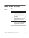
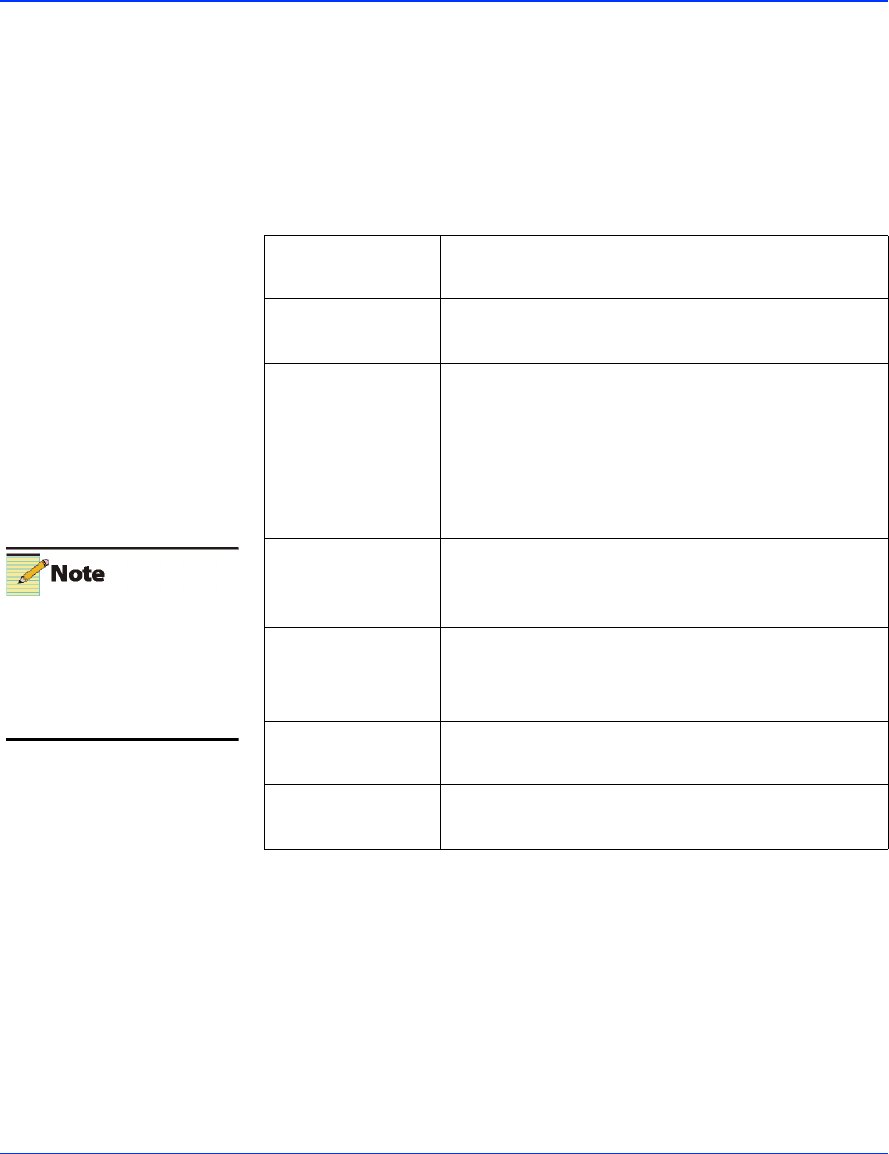
Indicators
and Controls
Function
Power LED The green power LED indicates that the DNH-6800 is
powered on.
Channel LEDs Each channel has a pair of LEDs, one green and one
red.
• The green LED lights when signal transmission is
occurring on that channel.
•The red LED briefly lights when a signal collision
occurs on that channel.
Jamming LED The jamming process occurs in conjunction with the
collision detection feature and is indicated by a red
LED.
Channel 0 Disable
Jumper
Channel 0 is disabled with this jumper.
This allows each DNH-6800 module within a single
frame to act independently.
Configuration LED In the event of a configuration failure, this LED
remains continuously lit.
Reset Button The Reset button is used to reset the DNH-6800
module after a configuration failure.