


E–16
When using a Macintosh with the projector, set the DIP switches of
the supplied pin adapter according to your resolution. After setting,
restart your Macintosh.
See the following pages for setting of the DIP switches.
• When using with a Macintosh, SVGA(800ן600 :MT840)/
XGA(1024ן768 : MT1040/MT1045) is recommended if your
Macintosh supports this mode.
• When using with a Macintosh PowerBook, output may not be
set to 800ן600 unless “mirroring” is off on your PowerBook.
Refer to owner’s manual supplied with your Macintosh com-
puter for mirroring.
NOTE: A Video Adapter cable manufactured by Apple Computer is
needed for a PowerBook which does not have a mini D-Sub 15-pin
connector.
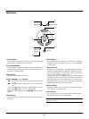
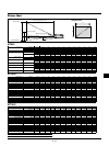
Settings for Monitor Mode
Number of DIP switch
1 23 456
Resolution
13" multi-scan mode /16"-13" ON ON ON ON
17" multi-scan mode /19"-13" ON ON ON
21” multi-scan mode /21"-13" ON ON ON
13" fixed mode /640x480 ON ON
VGA/SVGA mode ON ON
16" fixed mode /832x624 ON ON
19" fixed mode /1024x768 ON ON
21" fixed mode /1152x870 ON ON ON ON
NOTE: For settings other than display modes supported by your
Macintosh and the projector, use of the DIP switch may bounce an
image slightly or may display nothing. If this happens, set the DIP
switch to the 13" fixed mode and then restart your Macintosh. After
that, restore to a displayable mode and then restart the Macintosh
again. Make sure that the projector and your Macintosh are con-
nected with the pin adapter and the supplied signal cable (mini D-
Sub 15-pin connector) and then restart your Macintosh.
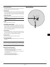
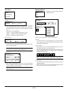
Examples of DIP switch setting
17" multi-scan mode VGA/SVGA mode 19" fixed mode
NOTE: Refer to your computer’s owner’s manual for more informa-
tion about your computer’s video output requirements and any spe-
cial identification or configuring your projector’s image and moni-
tor may require.
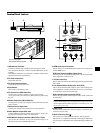
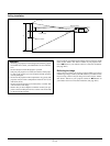
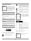
Connecting Your DVD Player
You can connect your projector to a DVD player with component
outputs or Video output. To do so, simply:
1. Turn off the power to your projector and DVD player.
2. If your DVD player has the component video (Y,Cb,Cr) output,
use the optional 15-pin-to-RCA x 3 cable to connect your DVD
player to the RGB INPUT connector on the projector.
For a DVD player without component video (Y,Cb,Cr) outputs,
use common RCA cables (not provided) to connect a composite
VIDEO output of the DVD player to the Video Input of the pro-
jector.
3. Turn on the projector and the DVD player.
NOTE: Refer to your DVD player’s owner’s manual for more infor-
mation about your DVD player’s video output requirements.
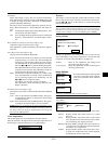
Connecting Your VCR Or Laser Disc Player
Use common RCA cables (not provided) to connect your VCR or
laser disc player to your projector. To make these connections, sim-
ply:
1. Turn off the power to the projector and VCR or laser disc player.
2. Connect one end of your RCA cable to the video output connector
on the back of your VCR or laser disc player, connect the other
end to the Video input on your projector. Use standard RCA audio
patch cords to connect the audio from your VCR or laser disc
player to the projector (if your VCR or laser disc player has this
capability). Be careful to keep your right and left channel connec-
tions correct for stereo sound.
3. Turn on the projector and the VCR or laser disc player.
NOTE: Refer to your VCR or laser disc player owner’s manual for
more information about your equipment’s video output requirements.
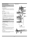
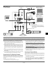
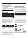
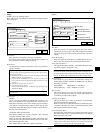
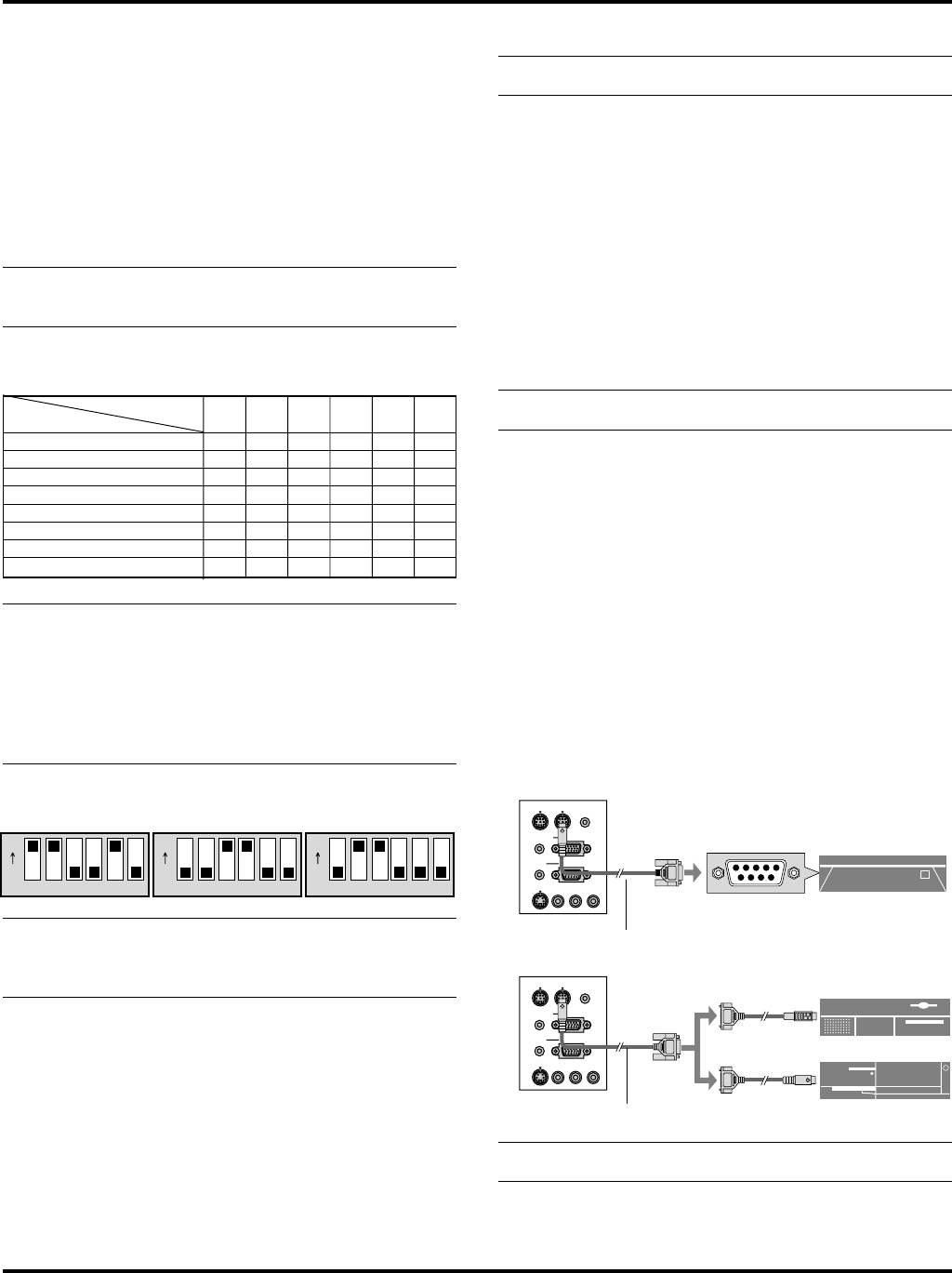
Connecting Your Computer to the Mouse Output Port
The built-in remote mouse receiver enables you to operate your
computer’s mouse functions from the remote control. It is a great
convenience for clicking through your computer-generated presenta-
tions.
To connect the mouse output port:
1. Turn off your computer.
2. For PCs: Remove your current mouse and connect the supplied
serial cable from the mouse output to your PC’s mouse port. (Use
the 6-pin adapter for connecting to a PS/2 computer.)
For Macintosh: Remove your current mouse from your computer,
attach the Macintosh adapter to the mouse output port’s serial cable,
and connect the projector to your mouse port.
3. When the built-in remote mouse receiver is available, it will dis-
able your regular mouse, disconnect the serial cable and restart
your computer.
321
ON
654321
ON
654 321
ON
654
PC CONTROL
REMOTE
CONTROL
INPUT
MOUSE
OUTPUT
S-VIDEO
VIDEO
AUDIO RGB INPUT
AUDIO MONITOR
OUTPUT
RGB OUTPUT
L
/
MONO
R
PC CONTROL
REMOTE
CONTROL
INPUT
MOUSE
OUTPUT
S-VIDEO
VIDEO
AUDIO RGB INPUT
AUDIO MONITOR
OUTPUT
RGB OUTPUT
L
/
MONO
R
Serial cable (Supplied)
Serial cable (Supplied)
IBM PC/AT
Macintosh
IBM PS2
NOTE:Some computers or software programs may not work with the
MOUSE OUT port.