114200-E Rev 00
Index-1
Numbers
10/100BASE-Tx
pin assignments, C-7
100BASE-Fx, 1-9
interface, connecting to, 1-13
10BASE-T
interface, connecting to, 1-12
7934, 50-pin to RS-232 cable, D-5
A
acronyms, xxi
adapter modules
connecting to
DSU/CSU interfaces, 1-18, 1-19, 1-21
ISDN interfaces, 1-17
serial interfaces, 1-17
V.34 interface, 1-20
DSU/CSU LEDs, 3-7, 3-8
interface options, 1-9, C-3
ISDN LEDs, 3-7
locating, 1-9
serial LED, 3-6
V.34 LEDs, 3-9
Adapter1 LED, 3-3
Adapter2 LED, 3-3
address settings, IP
DSU/CSU, A-3
Ethernet, A-4
serial, A-3
token ring, A-5
Annex A, frame relay, A-3
Annex D, frame relay, A-3
ARN
dimensions, C-1
installing, 1-5 to 1-8
in a rack, 1-6 to 1-8
on a flat surface, 1-5
interfaces, C-4
monitor
boot process and, 2-6
logging in to, 2-7
using, 2-6
operating, 3-1 to 3-10
power switch, using, 3-11
resetting, 3-12
space required to install, C-1
arn.exe file, 2-1
AUI
interface, connecting to, 1-11
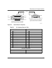
pin assignments, C-6
B
back panel
LEDs, 3-8
V.34 interface, connecting to, 1-29
Base LED, 3-3
base module
diagnostic LEDs, 3-2, 3-3
Ethernet interface
10BASE-T, 1-9
AUI, 1-9
Ethernet LEDs, 3-3
fiber interface
Fiber interface, 1-9
interface options, 1-9, C-3
locating, 1-9
serial LEDs, 3-6
token ring interface, 1-9
token ring LEDs, 3-4
B-channel #1 (B1) LED, 3-7
Index


