


Nautica 4000 Installation Guide
119500-A Rev. A
7
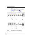
Connect the cables to the Nautica 4000 in the following sequence:
1. Connect one end of the black ISDN cable (labelled
119071) to one of the ISDN ports on the back of the
Nautica 4000. Connect the other end of the cable to the
ISDN wall outlet. Repeat this process for each ISDN
connection.
In North America, if you are using the RJ-45 to RJ-11
ISDN cables (labelled 119068), connect the RJ-45 end of
the cable to the back of the Nautica 4000. Connect the
RJ-11 end of the cable to the ISDN wall outlet. Repeat
this process for each ISDN connection.
2. Connect one end of the Ethernet cable (labelled 118138)
to the back of the Nautica 4000 and connect the other end
to your hub. Or, connect your transceiver or transceiver
drop cable (not supplied) to the LAN AUI port on the
back of the Nautica 4000 and connect the other end to
your Ethernet connector.
3. Connect the power cable to the port on the back of the
Nautica 4000. Turn the Nautica 4000 on by using the
on/off switch on the back of the unit.
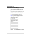
4. The Manager port is used for diagnostics only. The
Manager cable is labelled 117239. Connect this cable only
if you are an experienced user of Nautica products and
you want to start a Telnet or HyperTerminal session with
the Bay Command Console (BCC
TM
).
Danger: Disconnect all ISDN cables from the wall outlets
before connecting them to, or disconnecting them from, the
Nautica 4000.