


Chapter 1 Hardware overview 25
Nortel VPN Router Installation — VPN Router 1010/1050/1100
Rear view of the gateway
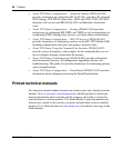
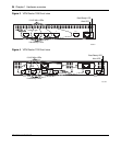
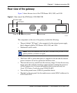
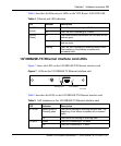
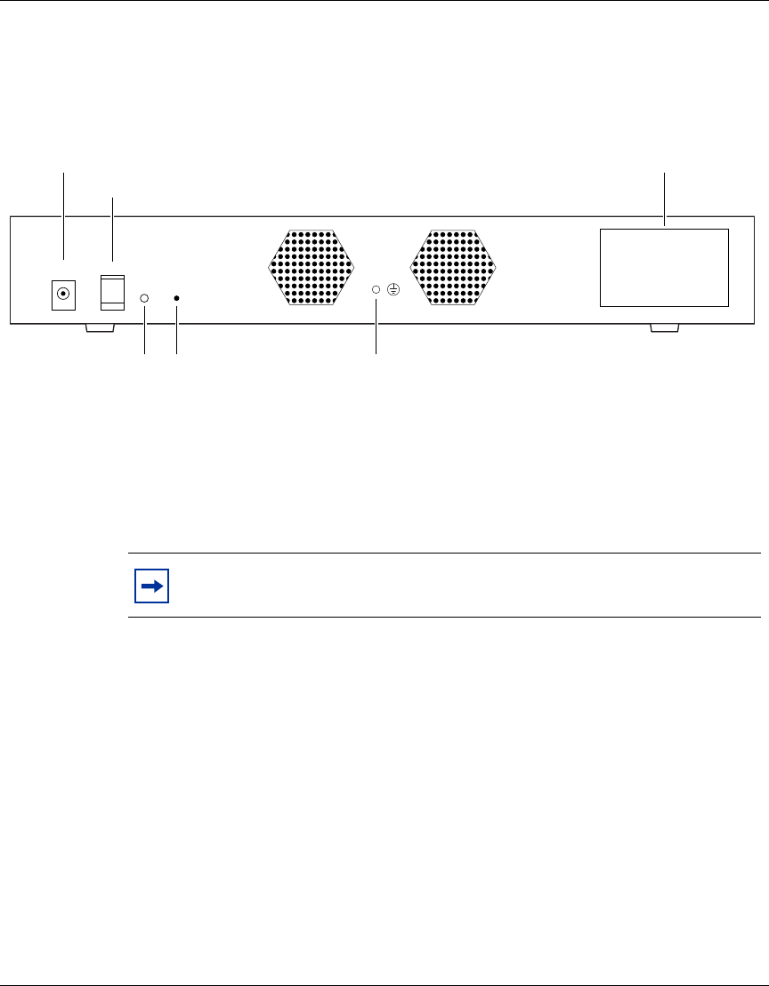
Figure 5 shows the rear view of the VPN Router 1010, 1050, and 1100.
Figure 5 Rear view of the VPN Router 1010/1050/1100
The components on the rear of the gateway include the following:
• The port labeled “DC Input” is the receptacle for the external power supply
that is shipped with the VPN Router 1010, 1050, and 1100.
• Mechanical on/off switch.
• The Power LED is green when power is supplied to the unit and the internal
power converters are not in a protective shutdown state.
• The recessed recovery switch boots the recovery image. To boot the recovery
image, press the switch by inserting a paper clip into it during the power-on
self-test memory test. For more information about system recovery, see
Nortel VPN Router Troubleshooting (NN46110-602).
• You use the ground screw (GND) to ground the chassis.
• The label on the rear panel lists the media access control (MAC) addresses for
LAN 0 and LAN 1.
Note: Nortel recommends that you wait 5 seconds after you turn off the
gateway before you turn it on again.
10679EA
DC Input
19V/3.16 A
60W max.
Power RC
DC power supply
On/Off switch
Power LED Recovery switch Ground screw
LAN0 Private MAC Address
LAN1 Public MAC Address
Label
1
0