


Chapter 1 Hardware overview 33
Nortel VPN Router Installation — VPN Router 1010/1050/1100
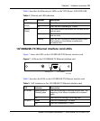
Table 9 describes the LEDs on the T1/E1 CSU/DSU WAN interface card.
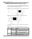
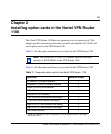
Single V.35/X.21 WAN interface card LEDs
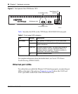
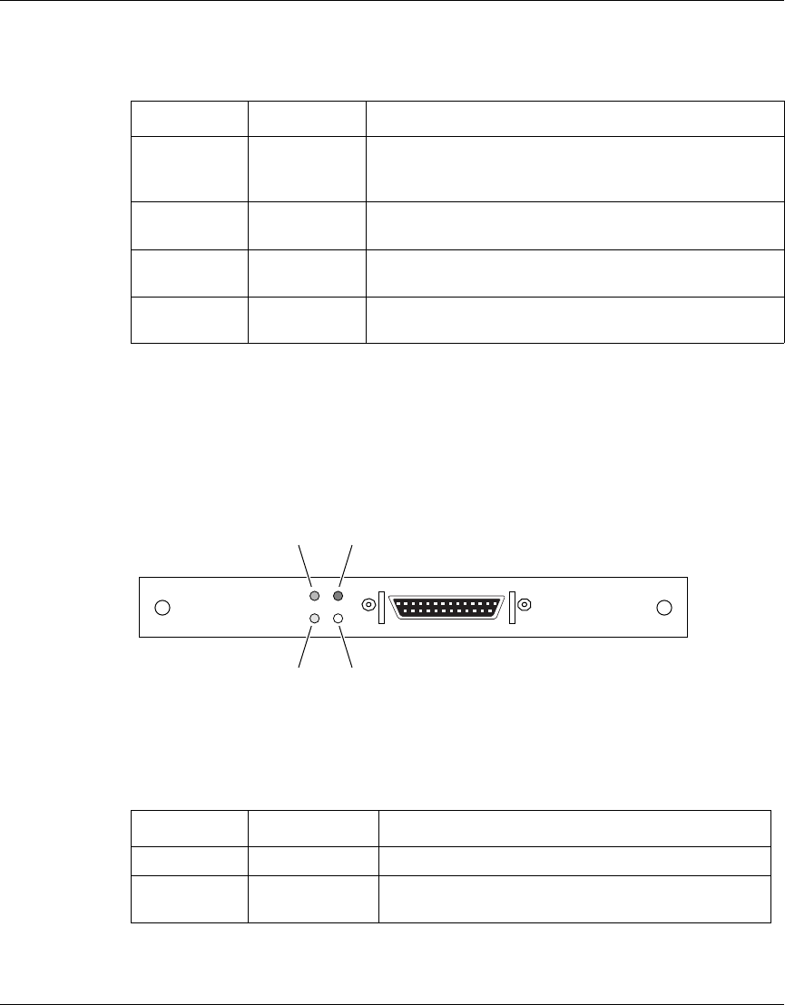
Figure 13 shows the LEDs on the single V.35/X.21 WAN interface card.
Figure 13 LEDs on the single V.35/X.21 WAN interface card
Table 10 describes the LEDs on the single V.35/X.21 WAN interface card.
Table 9 LED indicators on the T1/E1 CSU/DSU WAN interface card
LED Indicator Description
LED 1 Red The red alarm LED is lit when a loss-of-signal (LOS) or
out-of-frame (OOF) condition is detected on the receive
signal.
LED 2 Blue The blue alarm LED is lit when receiving an upstream
failure denoted by an alarm indication signal (AIS).
LED 3 Yellow The yellow alarm LED is lit when the far-end equipment
is in the red alarm condition.
LED 4 Green The green LED is lit when the condition is normal
operation.
Table 10 LED indicators on the single V.35/X.21 WAN interface card
LED Indicator Description
LED 1 Red No external transmit clock source is available.
LED 2 Green The signals CDC and DSR are on between the DSU
and the adapter. LED 2 detects receive link status.
CS160011A
LED 4, Green LED 3, Green
LED 1, Red LED 2, Green