


Operation, administration, and maintenance (OAM) features 2-15
Planning and Ordering Guide—Part 1 of 2 NTRN10AN Rel 12.1 Standard Iss 1 Apr 2004
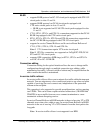
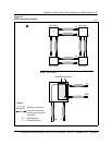
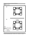
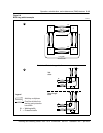
BLSR single span Fiber cut example
Step Action
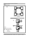
6 Node 4 receives the message on the long path, and enters into a ‘
Bridged
’
state. Node 4 bridges traffic from the incoming working channels to the
opposite direction, outgoing protection channels. Node 4 acknowledges
receipt of the message by sending a ‘
Bridged
’ message back to Node 3 on
the Long Path.
• source node (Node 4)
• destination node (Node 3)
• type of switch request (Signal Degrade)
• path direction (Long)
• node status (’
Bridged
’)
Note:
Nodes 1 and 2 remain in the ‘
Passthrough
’ state.
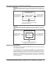
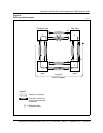
7 Node 3 receives the ‘Signal Degrade’ request from Node 4, and enters into a
‘
Bridged
’ state. Node 3 bridges traffic from the working to the protection
channels and acknowledges receipt of the message by sending a ‘
Bridged
’
message back to Node 4 on the Long Path.
• source node (Node 3)
• destination node (Node 4)
• type of switch request (Signal Degrade)
• path direction (Long)
• node status (’
Bridged
’)
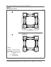
8 Node 4 receives the ‘
Bridged
’ status indication from Node 3. Node 4 enters
into the ‘
Bridged and Switched
’ state. Traffic received on the protection
channels are then routed as if they were received from the failed working link.
Node 4 then sends a message to Node 3 indicating that it has entered into
the ‘
Bridged and Switched
’ state.
• source node (Node 4)
• destination node (Node 3)
• type of switch request (Signal Degrade)
• path direction (Long)
• node status (’
Bridged and Switched
’)
Note:
Depending on the cross-connects provisioned, Node 4 will then either
drop traffic at the add/drop multiplexer or route traffic back out onto the
working channels of the ring.
—continued—