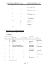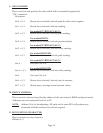
d. INPUT RANGE BIT NO. VALUE FREQUENCY/PULSE (FP)
0 0 ----
1 Low input level
1 0 ----
1 Debounce contact
2 0 ----
1 3K pull up to 5V
3 0 ----
1 1K pull down
5-4 00 12.5V excit.
01 5V excit.
10 8V excit.
11 not used
7-6 not used
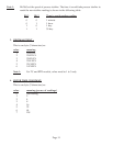
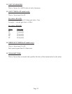
2. INPUT/OUTPUT CONFIGURA
TION:
This is one byte data (2 characters).
Bit pattern is:
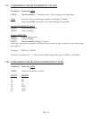
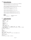
BIT NO. VALUE MEANING
TC/RTD ACV/ACC/ST PR FP
1-0 00 Degree C ---- ----
01 Degree F ---- Freq. mode
10 Degree K ---- Totalizer ----
11 Degree K ---- Totalizer Freq. mode
2 0 Temp. compensation ---- See Note 1 ----
1 No temp compensation---- See Note 1 Quadrature
3 0 ---- ---- See Note 1 ----
1 ---- ---- See Note 1 A-B mode
4 0 ---- ---- ---- ----
1 ---- ---- ---- Totalize mode
5 0 ---- ---- ---- ----
1 ---- ---- Square root ----
7-6 not used set to 0
Page 10


