


Page 21
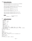
DRX-FPSPECIFICATIONS
INPUT TYPE:
Min. Low level signal input (magnetic
pickups) : From 0 mV to 120 mV
Open Collector NPN (Use software to set:
3 KΩpull up to 5V): Max. current source = 1.66 mA
Open Collector PNP (Use software to set: 1KΩ pull down to RTN):
Max. current sink = 12.5 mA
TTL/CMOS Input: (Use software to set: no pull up/down).
Low <= 0.8 V , High >= 3.5 V (For Input: 0.2 Hz to 16 KHz)
Low <= 0.8 V , High >= 12 V ( For Input: 0.2 Hz to 50 KHz )
NAMUR Sensors (Use software to set: 1KΩpull
down to RTN and 8.2V Excitation.)
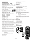
For measuring a low level signal riding on top of a
large DC signal, connect a 0.1 uF capacitor. See
Detail.Use software to set 1KΩ pull down to RTN.
OPERATING MODES:
Frequency: Range = 0.2 Hz to 50 KHz
Max. Input Frequency: 30 KHz. for Input Level: 0-5 V
Max. Input Frequency: 50 KHz. for Input Level: 0-12 V
FREQUENCY
RESOLUTION
0 to 9.99999 Hz 0.00001 Hz
10 to 99.9999 Hz 0.0001 Hz
100 to 999.999 Hz 0.001 Hz
1000 to 9999.99 Hz 0.01 Hz
10000 to 50000.0 Hz 0.1 Hz
0 to 50000 Hz 1 Hz
Totalize with Reset: Range = 0 to 999999*, if reading is larger
than 999999, then reading is converted to floating point
number, i.e. 9.99E9 (maximum).
Max. Input Frequency: 30 KHz. for Input Level: 0-5 V
Max. Input Frequency: 50 KHz. for Input Level: 0-12 V
A-B Totalize (Reset input used as +Ainput): Range = -99999
to 999999*, if reading is larger than 999999, then reading is
converted to floating point number, i.e. -9.99E9 (minimum),
9.99E9 (maximum).
Max. Input Frequency: 30 KHz. for Input Level: 0-5 V
Max. Input Frequency: 25 KHz. for Input Level: 0-12 V
Quadrature (Reset input used as second input): Range =
-99999 to 999999*, if reading is larger than 999999, then reading
is converted to floating point number, i.e. -9.99E9 (minimum),
9.99E9 (maximum).
Max. Input Frequency: 30 KHz. for Input Level: 0-5 V
Max. Input Frequency: 25 KHz. for Input Level: 0-12 V
* Resolution is 1 count.
ISOLATION:
Dielectric strength to 1000 Vrms transient per 1 minute test
based on EN 61010 for 50 Vdc or Vrms working voltage.
Three way Isolation:
• Power to input
• Power to analog output/communication
• Input to analog output/communication
INPUT IMPEDANCE:
Input: 1MΩ to +EXC
Reset: 100K to +5V
INPUT OVER-VOLTAGE PROTECTION:
With 1K pull down: 14V
With 3K pull up: 20V
Without pull up/down: 60V
EXCITATION:
5, 8.2 or 12.5V at 25mA, programmable
ACCURACYAT25 °C:
± 0.1% of FS Crystal time base accuracy: ± 50 ppm
TEMPERATURE STABILITY:
± 50 ppm/°C typical Time base stability: ± 1ppm/°C
STEPRESPONSE FOR RS485 OUTPUT:
0.1 second to 99% of the final value
(Filter time constant = 0, Gate time = 0.05 Sec)
RESPONSE TIME:
To verify the response time, check the carriage return <CR>, it will be
sent at the end of the response. You can send another command after
you receive the <CR>.
i.e. send: *01X01
response: 01X01<DATA><CR>
Note: Only for reading (X01 command).
01 is address.
Frequency mode: response time is controlled by the gate time. If
gate time is increased then response time is longer. Other modes:
response time is not controlled by the gate time.
WARM UPTO RATED ACCURACY:
30 minutes
INPUT POWER:
10 to 32 Volt DC
POWER CONSUMPTION:
3 Watts (125mAat 24V DC)
OPERATING AMBIENT:
-5 to +55 °C
STORAGE TEMPERATURE:
-40 to +85 °C
RELATIVE HUMIDITY:
90% at 40 °C non-condensing
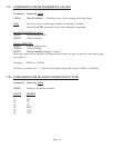
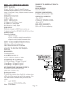
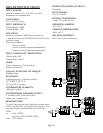
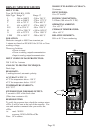
+EXC
+IN
RST
RTN
Frequency Mode/
Quadrature Mode
Excitation
NPN open
Collector
Totalize Mode
with Reset (example)
+
-
N/C
SIGNAL INPUT
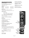
D
C
P
W
R
1 2
J4
J2
J3
J1
34
PWR
R
S
4
8
5
-TX
-RX
+TX
+RX
TER
R
S
4
8
5
1 2 3 4
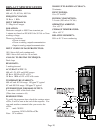
+EXC
+IN
RST
RTN
J2
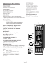
1 2 3 4
+EXC
+IN
RST
RTN
J2
Quadrature Mode
Excitation
Quadrature
Encoder
A
B
EXC
EXC
A
B
Totalize (A-B) Mode
J1
ø
120mV
1 2 3 4
+IN
0.1uF
RTN