


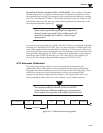
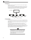
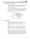

5.9 Input and Source Impedance
As illustrated below, the input impedance (Ri) of an analog-to-digital converter
combines with the transducer’s source impedance (Rs) forming a voltage
divider. This divider distorts the voltage being read at the analog-to-digital
converter. The actual voltage read is represented by the equation:
VADC = VT x Ri / (Rs + Ri)
The input impedance (Ri) of most ADCs is at least 1 MΩ; low source impedance
(Rs) usually presents no problem. Some transducers, such as piezoelectric types,
have high source impedance, and should therefore be used with a charge-
sensitive amplifier of low output impedance. As described in the following
paragraphs, multiplexing can greatly reduce the effective input impedance of an
analog-to-digital converter.
Figure 5-5. Analog to Digital Converter
5.10 Crosstalk
Crosstalk is a type of noise related to source impedance and capacitance, in
which signals from one channel leak into an adjacent channel, resulting in
interference or signal distortion. The impact of source impedance and stray
capacitance can be estimated by using the following equation.
T = RC
Where T is the time constant, R is the source impedance, and C is the stray
capacitance.
High source (transducer) impedance can be a problem in multiplexed A/D
systems. When using more than 1 channel, the channel input signals are
multiplexed into the A/D. The multiplexer samples each signal and then
switches to the next input signal. A high-impedance input interacts with the
multiplexer’s stray capacitance and causes crosstalk and inaccuracies in the A/D
sample.
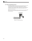
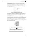
A solution to high source impedance in relation to multiplexers involves the use
of buffers. The term buffer has several meanings; but in this case, buffer refers to
an operational amplifier having high input impedance but very low output
impedance. Placing such a buffer on each channel (between the transducer and
the multiplexer) prevents the multiplexer’s stray capacitance from combining
with the high input impedance. This use of a buffer also stops transient signals
from propagating backwards from the multiplexer to the transducer.
Signal Management
5
5-7