


16
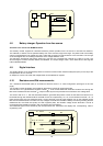
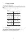
P
D/A
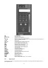
Keyboard
1000 mV
100 mV
54 mV
22 mV
Out
µ
x 1000 multipl.
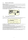
4.8 Battery charger. Operation from line source
A
TTENTION
:
ONLY FOR USE WITH
N
I
-MH B
ATTERIES
.
The auxiliary module, supplied as a standard accessory, allows operation from 110-120 Vac or 220-240 Vac 50/60 Hz.
The calibrator, if needed, can be operated directly from a line source through the charger. The plastic case of the battery
charger incorporates the line voltage plug and a cable with connector for interconnection to the instrument. The charger
circuit is designed with an insulating transformer and a voltage stabilizer circuit.
The step-down transformer reduces the power line (110-120 Vac or 220-240 Vac nominal) to a value of 10 Vac. The
above voltage is full wave rectified, filtered and stabilized. The output voltage of 6,6 V is the ideal value to recharge the
internal Ni-MH batteries.
4.9 Digital interface
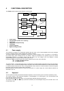
The digital interface circuit is essentially based on the serial communication interface subsystem (SCI) on the chip of the
microprocessor at 0 to +5V level.
An adaptor to convert TTL to RS 232 voltage levels can be obtained on request.
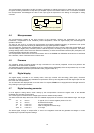
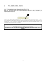
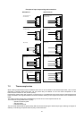
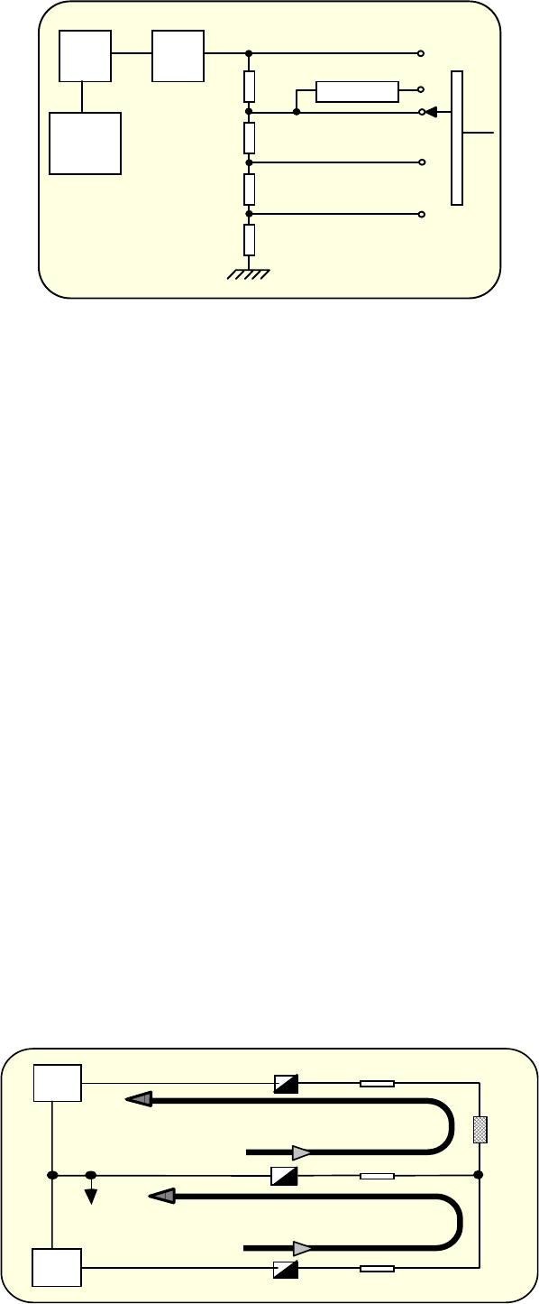
4.10 Resistance and Rtd measurements
The resistance thermometer (Rtd) is connected to terminals A-B-C in a 3-wire configuration (see figure on the next
page).
Two constant current generators are provided by the auxiliary module for supplying the Rtd.
The first half of “IC1” generates the negative current I
A
= - 0.25 mA that flows from terminal B to terminal A through the
Rtd and line resistances RLA and RLB. I
A
is kept constant by the microprocessor that controls the zero voltage level.
The second half of “IC 1”, with the associated resistors, generates the positive current I
C
that flows from terminal C to
terminal B through line resistances RLC and RLB. Current I
C
is kept exactly = 2 x I
A
, so the resultant current I
B
= I
C
- I
A
flows through RLB. The input measured signal across terminals A and B is the algebraic sum of drop voltages across
Rtd and line resistances RLA and RLB. As drop voltages across RLA and RLB are exactly the same (providing that line
resistances RLA and RLB are equals), but with opposite poles, the resultant voltage across terminals A and B is
proportional to Rtd resistance variation, with no influence of line resistance.
The measured signal is then handled by the microprocessor that linearizes it and displays the corresponding value in
engineering units.
Rtd
IC1/1
IC1/2
RLA
RLB
RLC
A
B
C
IC = + 0.5 mA
IB = IC - IA = + 0.25 mA
IA = - 0.25 mA