


Step Four Step Five
CALIBRATION
A. Introduction: The switch has two modes, the RUN and CAL
modes. In the RUN mode, the switch is operational and the relay(s)
will energize or de-energize at the calibrated set point distances. In the
CAL mode, the relay set point distances and states may be target-cal-
ibrated into memory. The switch arrives from the factory without
any preset calibration. Each relay channel may be user calibrated
into one of the following configurations; 1) high or
low level alarm,
2) high and
low level out of bounds alarm, 3) automatic fill or empty,
or 4) duplexing/Alternating.
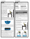
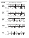
High or Lo
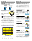
w Level Alarm: The high or
low level alarm is programmed with a sin-
gle set point at the desired tank level.
Configured as a high alarm, the relay will
energize if the level rises above the set
point. Configured as a low level alarm, the
relay will energize if the level falls below
the set point.
High and Lo
w Level Out of Bounds
Alarm: Programmed with two set points,
the high and low level out of bounds alarm
protects the top of the tank from overspill
and the bottom of the tank from run-dry. If
the level rises above or falls below the set
points, the relay will energize. The relay
will remain de-energized as long as the level
is in between the set points.
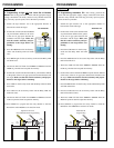
A
utomatic Fill or Empty: Programmed
with two set points, the latched automatic
fill or empty will control a pump or valve.
When the level reaches the energize set
point, the latching relay will energize, and
remain energized until the level reaches the
de-energize set point.
Duple
x/Alternate: Programmed with
three set points and two relays, duplexing
will automatically fill or empty the tank
with two pump alternation for maintenance
and lead-lag control for back up operation.
When the level reaches the energize set
point, the latching relay will energize, and
remain energized until the level reaches the
de-energize set point. Each time the level
reaches the energize set point, the relays will alternate. If the level
reaches the back-up energize set point, both relays will energize until
the level reaches the de-energize set point. Alternation will automati-
cally fill or empty the tank with two pumps switching after each cycle.
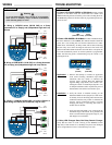
PREPARATION
A. Supply Voltage: The power supply voltage should never exceed
the maximum rating of 250 VAC for the LVCN700 series AC switch
or 28 VDC for the LVCN700-DC series switch.
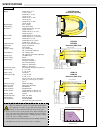
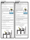
B. Conduit Entrance: The enclosure has two 1/2” NPT female
conduit ports for routing of the switch
supply and relay circuit wiring. Do not
run mixed AC and DC voltages
through the same conduit port. Route
the supply voltage circuit through one
port and the relay circuit(s) through the
opposite port.
C. Relay Fail-Safe Design:
The switch has (3) relay channels. Each relay is a SPDT
(single pole, double throw) type rated at 60 VA. Normally
open (NO) or normally closed (NC) operation is user
selected based on the desired system control and fail-safe
logic. Always design a fail-safe system that accommo-
dates for the possibility of relay and/or power failure. The "nor-
mal" relay state is where the relay coil is de-energized and the Red
relay LED is OFF. Therefore, if power is cut OFF to the switch it will
de-energize the relay. Make sure that the de-energized state is the safe
state in your system design. As such, if switch power is lost, a pump
will turn OFF if it is connected to the normally open side of the relay.
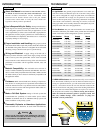
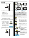
E. Maximum Applied Range: Individual or cumulative effects of
agitation, vapor or foam can reduce the overall quality of signal return
and shorten the maximum applied range of the switch. To determine
the maximum applied range of the switch in your application, refer to
the below derating chart.
VAC
INPUT
HOT
NEUTRAL
L
1
L
2
POWER
VAC
VDC
INPUT
Positive
Negative
(+) (-)
POWER
VDC
RELAY
1
LVCN700 series
shown
1/2 NPT
Conduit
Supply
Port
Relay
Port
50Khz
100Khz
012345678910
0%
50%
100%
Ultrasonic Derating Chart
LVCN704/709 LVCN716/726
Agitation = 1-3 @ 100 kHz Agitation = 1-3 @ 50 kHz
Vapor = 4-6 @ 100 kHz Vapor = 3-5 @ 50 kHz
Foam = 5-6 @ 100 kHz Foam = 4-6 @ 50 kHz
Energize
De-energize
High Alarm Shown
Energize
Energize
De-energize
De-energize (All) Low
Energize
(Backup)
High High
Energize
(Primary)
High
Energize
De-energize
(Auto-Fill Shown)
LVCN700-DC series
shown