


Step Ten
PROGRAMMING
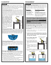
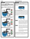
E. Programming Automatic Empty: After having powered the
switch with the appropriate supply voltage, entered the CAL mode,
selected a relay channel and erased any previously input set points,
follow the below procedure:
1. Stretch the tape measurer out to the appropriate distance in
between the switch and target.
2. Position the switch at the desired HIGH
set point distance defined as the lesser
of the two air gap spaces between the
transducer and the target. Make sure
that the switch is stationary and per-
pendicular to the target before con-
tinuing.
3. Press the HIGH button for the first key-
stroke and the Relay LED will blink
once.
4. Press the LOW button for the second key-stroke and the Relay
LED will blink twice.
5. The Power LED will flash from AMBER to GREEN when the
HIGH set point has been accepted into memory.
6. Position the switch at the desired LOW set point distance defined
as the greater of the two air gap spaces between the transducer and
the target. Make sure that the switch is stationary and perpen-
dicular to the target before continuing.
7. Press the LOW button for the first key-stroke and the Relay LED
will blink three times.
8. Press the HIGH button for the second key-stroke and the Relay
LED will blink four times.
9. The Power LED will flash from AMBER to GREEN when the
LOW set point has been accepted into memory.
10. Press SELECT to program the next relay channel or slide the
RUN/CAL switch RIGHT to exit the CAL mode.
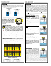
Automatic Empty
Box
Insert
Table
Target
Wall
Tape
Automatic Empty
Programming
High
Set Point
Distance
Low
Set Point
Distance
De-energize
Energize
2
6
Step Eleven
PROGRAMMING
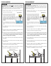
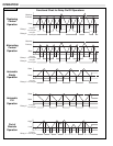
Programming Duplexing Pump Control: After having powered
the switch with the appropriate supply voltage, entered the CAL
mode, selected relay channel 1 and erased any previously input set
points, follow the below procedure:
1. Stretch the tape measurer out to the appropriate distance in
between the switch and target.
2. Position the switch at the desired HIGH
set point distance defined as the lesser
of the two air gap spaces between the
transducer and the target. Make sure
that the switch is stationary and per-
pendicular to the target before con-
tinuing.
3. Press the HIGH button for the first key-
stroke and the Relay LED will blink
once.
4. Press the LOW button for the second key-stroke and the Relay
LED will blink twice.
5. The Power LED will flash from AMBER to GREEN when the
HIGH set point has been accepted into memory.
6. Position the switch at the desired LOW set point distance defined
as the greater of the two air gap spaces between the transducer and
the target. Make sure that the switch is stationary and perpen-
dicular to the target before continuing.
7. Press the LOW button for the first key-stroke and the Relay LED
will blink three times.
8. Press the HIGH button for the second key-stroke and the Relay
LED will blink four times.
9. The Power LED will flash from AMBER to GREEN when the
LOW set point has been accepted into memory.
10. Press SELECT to program relay channel 2.
11. Position the switch at the desired HIGH HIGH set point distance
defined as the air gap space between the transducer and the target.
Make sure that the switch is stationary and perpendicular to
the target before continuing.
Duplex
Box
Insert
Table
Target
Wall
Tape
Duplex Programming
(Primary)
High
Set Point
Distance
Low
Set Point
Distance
De-energize (All) Low
Energize
(Backup)
High High
Energize
(Primary)
High
2
6