


Step Fourteen
High Alarm
VAC
INPUT
HOT
NEUTRAL
Motor Starter
(Pump)
RELAY
1
RELAY
2
RELAY
3
L
1
L
2
POWER
VAC
Cal. Run
High Low
Select
Low Alarm
VAC
INPUT
NEUTRAL
HOT
High Alarm
VDC
INPUT
HOT
NEUTRAL
Motor Starter
(Pump)
RELAY
1
RELAY
2
RELAY
3
(+) (-)
POWER
VDC
Cal. Run
High Low
Select
Low Alarm
VDC
INPUT
NEUTRAL
HOT
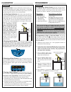
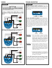
WIRING
Step Fifteen
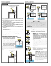
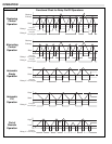
TROUBLESHOOTING
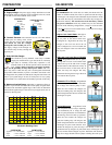
A. Power LED SOLID GREEN in RUN Mode: During normal
operation in the RUN mode, the Power LED will remain solid
GREEN indicating that the switch has power and is tracking the level.
The RED Relay LEDs will be ON or OFF as programmed per the cur-
rent level state.
B. Power LED AMBER in RUN Mode: If while in the RUN mode,
the Power LED turns solid AMBER, this indicates that the switch has
power, but is not tracking the level and has entered into it’s FAIL-
SAFE mode. Coincidently, all Relay LEDs will be OFF, indicating
that the relays are in their de-energized safe-state. The switch will
remain in the FAIL-SAFE mode until such time that it re-acquires the
level and automatically returns to normal operation as programmed.
Check the following points in determining why the switch is not
tracking the level:
RELAY
1
RELAY
2
RELAY
3
L
1
L
2
POWER
Alarm
VAC
INPUT
HOT
NEUTRAL
Motor Starter
(Pump 2)
RELAY
1
RELAY
2
RELAY
3
L
1
L
2
POWER
VAC
Cal. Run
High Low
Select
VAC
INPUT
NEUTRAL
HOT
Duplex/Alternation
Motor Starter
(Pump 1)
1. Observe and attempt to correlate an application
event such as foaming, substantial vapor and/or
turbulence that may reduce or eliminate the
acoustic signal strength. Read the Maximum
Applied Range (Step #4-E) and consider rein-
stalling the switch in a Stand-Pipe (Step #11-A-4)
to dampen turbulence and/or separate the point of
measurement from surface foam and/or vapor.
2. Verify the switch is installed correctly per the
INSTALLATION section (Step #11) of this manu-
al. Initially focus on the fitting and/or obstructions
within the beam that may reduce or eliminate the
acoustic signal transmission-receipt. Consider
changing the fitting or relocating the switch to
another area of the tank.
3. Verify that the tank height is not greater than the
maximum range of the switch. If so, purchase and
install a switch with the appropriate range for your
tank height or level distance.
Installation
Application
Green
(Solid ON)
RED
(Solid ON or OFF)
RELAY
1
RELAY
2
RELAY
3
L
1
L
2
POWER
Amber
(Solid ON)
RED
(All OFF)
C. Relay LED Changes State, But Relay Doesn’t Change:
Verify that the switch is wired correctly per the WIRING section
(Step #12) of this manual. If so, the Relays may have been damaged
due to a high inductive load or carbon build-up over time.
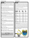
A. Wiring a LVCN700 series (95-250 VAC) to a Pump
(Automatic Fill or Empty) and (Independent High and Low)
Alarms
Warning
To prevent damaging the relays, the use of an appropriate
motor starter or secondary relay is ALWAYS recommended
when actuating pumps or valves.
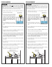
B. Wiring a LVCN700-DC (12-28 VDC) to a Pump (Automatic
Fill or Empty) and (Independent High and Low) Alarms
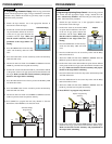
C. Wiring a LVCN700 (95-250 VAC) to Pumps (Duplex or
Alternating) and Alarm (Out of Bounds, High or Low)