


A. Fitting Selection: Check the switch part number
to determine the required fitting mount size and
thread type. The switch is commonly installed in
tank adapters, flanges, brackets or stand pipes.
1. Adapter: Select a tank adapter fitting with
minimal height so as to ensure that the
installed transducer will not be substantially
elevated into the fitting. Avoid tank adapter
styles with threads and/or pipe stops forward
of the installed transducer.
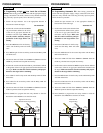
2. Flange: Tall flanges with narrow risers
impede the acoustic signal. Select a fitting
with the right riser height versus inner diame-
ter geometry. The switch may be elevated up
to 12” (30 cm) in a 6” (15 cm) riser, 8” (20
cm) in a 4” (10 cm) riser and 3” (7.6 cm) in a
2” (5 cm) riser.
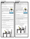
3. Bracket: A LVM-30 side mount bracket or
equivalent can be used for open tank top
installations against the side wall.
4. Stand Pipe: A stand pipe may be
used to dampen turbulence or separate
surface foam. Select a 2” or larger
pipe for model LVCN704/709. Select
a 3” or larger pipe for model
LVCN716/726. The pipe length
should run the measurement span. Cut
a 45° notch at the bottom of the pipe
and drill a 1/4” pressure equalization
hole high in the dead band.
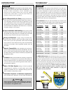
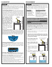
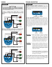
Step Thirteen
INSTALLATION
Adapter
VACUUM
Do not install at
angle relative
to the liquid
Do not install with-
in 3” of
tank side wall
Do not install
with objects
in the beam
Do not install
in applications
with vacuum
Warning
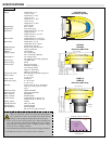
Install the appropriate installation fitting. Make sure that
the fitting and switch threads are not damaged or worn.
Install the switch with the included Viton mounting gasket.
Hand tighten the switch within the fitting. Perform an
installed leak test under normal process conditions prior to
system start up.
Gasket
Flange
on Riser
Height
Inner Diameter
Riser
Bracket
Stand Pipe
Dead Band
Ventilation
Hole
Operational Range
Highest
Liquid Level
Lowest
Liquid Level
2"/3" Minimum
Diameter
Step Twelve
PROGRAMMING
12. Press the HIGH button for the first key-stroke and the Relay LED
will blink once.
13. Press the HIGH button again for the second key-stroke and the
Relay LED will blink twice.
14. The Power LED will flash from AMBER to GREEN when the set
point has been accepted into memory.
15. Press the SELECT switch repeatedly until BOTH LEDs for Relay
1 and Relay 2 are ON (after Relay 3).
16. Press the HIGH button for the first key-stroke and Relay LED will
blink once.
17. Press the HIGH button again for the second key-stroke and Relay
LED will blink twice.
18. Press SELECT to program the next relay channel or slide the
RUN/CAL switch RIGHT to exit the CAL mode.
Note: The duplexing mode can be disabled by repeating Steps #15-18
and pressing the LOW button instead of the HIGH button in the
HIGH/HIGH combination.
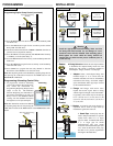
Programming Alternating Control Only:
1. To program the switch for alternating
control only without the lead-lag func-
tion, follow the instructions for
Programming Duplexing Pump Control
(Steps 11 and 12). The difference
between Duplexing and Alternation is
the location of the Relay 2 set point. Set
Relay 2 close to the deadband without
crossing into the deadband and above
the highest level of expected liquid.
Note: The alternation mode can be disabled
by repeating Steps #15-18 and pressing the
LOW button instead of the HIGH button in the HIGH/HIGH combi-
nation.
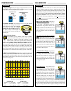
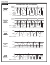
Duplex Programming
(Backup)
Box
Insert
Table
Target
Wall
Tape
Distance
Set Point
De-energize (All) Low
Energize
High
High High
Alternating
11
Alternating Programming
(Backup)
Box
Insert
Table
Target
Wall
Tape
Distance
Set Point
2
Programming Duplex Pump Control (continued):