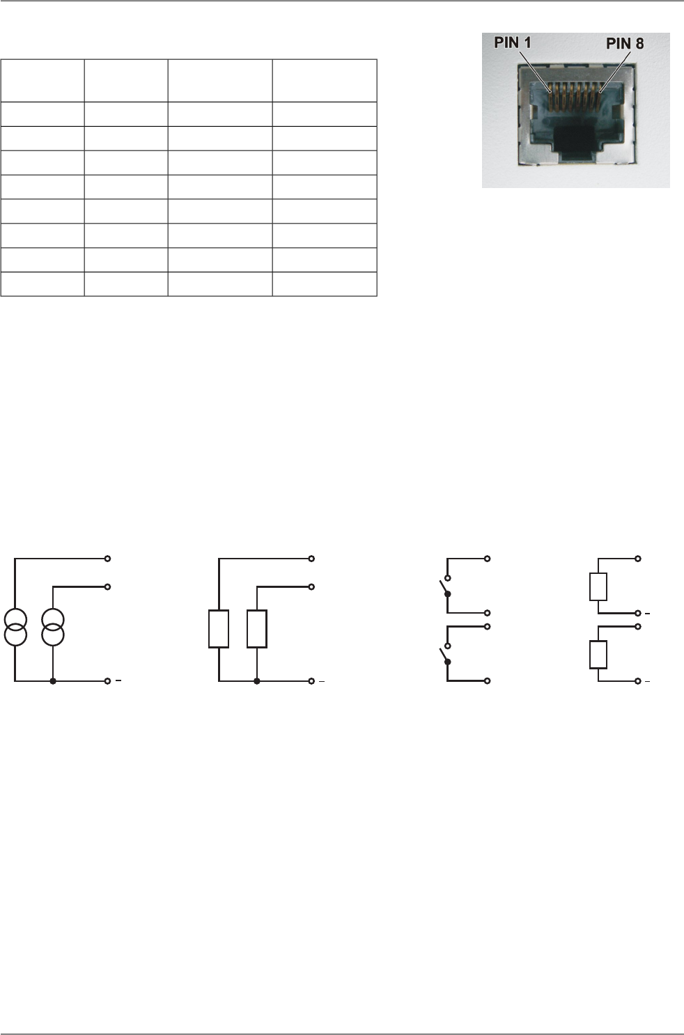
Fig. 3.4: RJ-45F
Tab. 3.4: Table of Ethernet to cable connector connections
Crossed
cable
Direct cableSignalPIN
white - greenwhite - orangeTX+1
greenorangeTX-2
white - orangewhite - greenRX+3
blueblue—4
white - bluewhite - blue—5
orangegreenRx-6
white - brownwhite - brown—7
brownbrown—8
3.4. Analog and Digital Inputs and Outputs
The board of analog and digital inputs and outputs (ADIO module) is designed for :
• creating 20 mA current loops
• switching loads supplied with DC and AC current
• scanning digital signals
Each functional group of terminals is galvanically separated from the rest of the device as shown on
the internal layout diagram for the ADIO module on the image below:
+A OUT 0 +A IN0
+A OUT 1 +A IN1
A IN0,1 DIN1
+DIN1
A OUT 0,1
DIN0DOUT 0
+DIN0DOUT 0
DOUT 1
DOUT 1
Analogoutputs Analoginputs DigitalinputsDigitaloutputs
Fig. 3.5: Wiring diagrams for analog and digital inputs and outputs
3.4.1. Labelling
Individual terminals of terminal blocks are labelled:
Connector A OUT - analog outputs
Connector A IN - analog inputs
Connector D OUT - digital outputs
Connector D IN - digital inputs
Wideband modems – PROFI MX160 – © RACOM s.r.o.12
Connectors


