• data connector – DSUB9 (Canon) – marked NMEA
Antenna connector for an active antenna – the antenna supply to the antenna connector is short-circuit
proof
Tab. 3.8: Connection of data cable
RS232 signalDSUB9F
pin
+3,3 V through 10 k resistor1
data NMEA output2
see Note3
input ALARM 0 (from sw v. 8.05)4
GND5
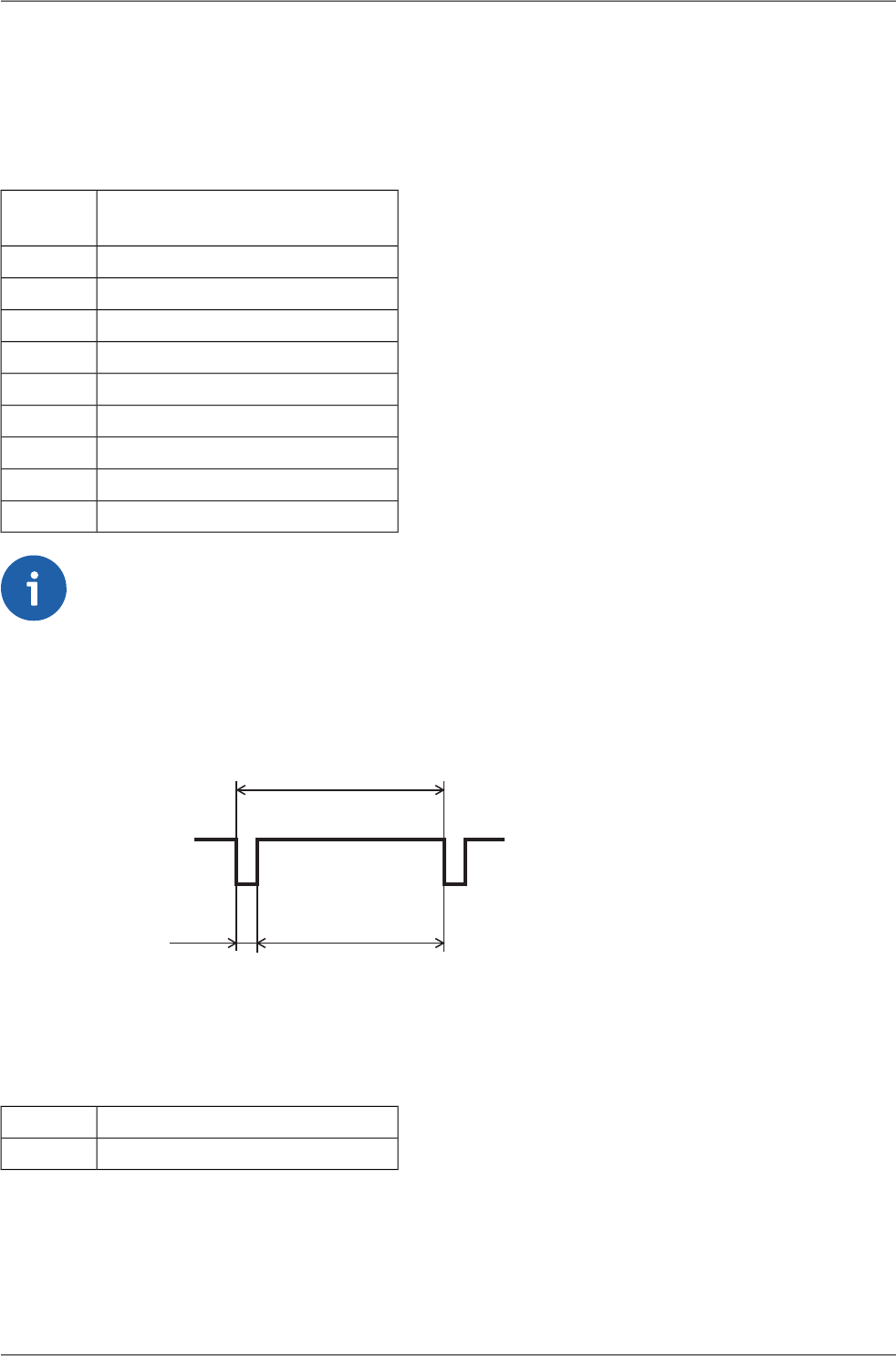
output 1 PPS (pulse per second)6
input ALARM 17
see Note8
unwired9
Note
Inputs ALARM 0, 1 are passive, a positive 3-15 V voltage should be applied for accepting
functions. For the contact activacion can be connect the positive potential from pin No.
1.
•
• Pin No. 3 becomes the input for configuration data, if we connect pin No. 8 to GND.
• The behaviour of time pulses at pin No. 6 (default)
+6V
1s
100ms
-6V
900ms
Meaning of LED colours
Tab. 3.9: Meaning of GPS module LEDs
TP – Time Pulsered
St – Status (in progress)green
The GPS is providing the correct data if the red LED is flashing to the rhythm of time pulses (typically
1 s).
Wideband modems – PROFI MX160 – © RACOM s.r.o.16
Connectors


