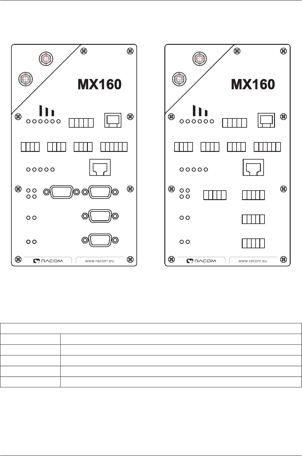
3.11. View of Radio Modem
POWER
RF Tx
Rx Rx
Tx Tx
POWERON
RFSYNC
+
+
PI
GND
GND
Rx
Tx
100
LINK
F.D.
SERVICE
ETH0
+
+
+
+
+
+
+
+
+
–
–
–
–
–
–
–
–
–
A OUT
A IN DOUT DIN
UP
1
1 1 1
0
0 0 0
Rx
Tx
3
2
SCC2
SCC3
SCC0
SCC1
Rx
Rx
Tx
Tx
POWER
RF Tx
POWERON
RFSYNC
+
+
PI
GND
GND
SCC0
SCC1
Rx
Rx
Rx
Tx
Tx
Tx
100
LINK
F.D.
SERVICE
ETH0
SCC2
SCC3
Rx
Tx
3
2
+
+
+
+
+
+
+
+
+
–
–
–
–
–
–
–
–
–
A OUT
A IN DOUT DIN
UP
1
1 1
1
1
0
0 0 0
CTS
RTS
TxD
RxD
GND
CTS
RTS
TxD
RxD
GND
2 3 4 5
1 2 3 4 5
SLOT
1
SLOT
2
SLOT
3
SLOT
4
SLOT
5
Fig. 3.15: View of radio modem — description of connectors, model with DSUB (Canon) connectors
and with terminals
Tab. 3.14: Slot options
Optional modules
ADIO (analog and digital inputs and outputs)slot 5
Ethernet 10/100 Mbpsslot 4
2×RS232slot 3
RS232 or galv.sep. RS232 or RS422/RS485 or GPS or M-BUS or TPORTslot 2
RS232 or galv.sep. RS232 or RS422 or GPS or M-BUS or TPORTslot 1
21© RACOM s.r.o. – Wideband modems – PROFI MX160
Connectors


