


10400276-003 06/2010 ©2010 Overland Storage, Inc. Page 2 of 6
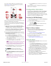
c. Release and slide the middle member back into
the outer member.
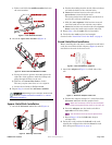
Figure 3. Inner Rail Release Latch
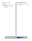
3. Attach the right inner member (Figure 4):
Figure 4. Attach Inner Rail Member to E2000
a. Facing the chassis, position the rail against the
right side of the appliance with the locking tabs
going through the holes on the rail.
b. Slide the rail toward the front to lock it.
This may require some force as it is a tight fit.
c. Secure the rail with its Phillips screw.
4. Repeat Step 3 to install the left inner member.
IMPORTANT: Depending on your rack type, continue with
either the “Square-Holed Rack Installation” or “Round-
Holed Rack Installation.”
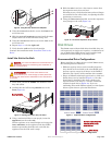
Square-Holed Rack Installation
1. Attach the left outer rail to the rack (Figure 5):
Figure 5. Attaching Front of Rail
a. Position the rail against the inside of the rack front
rail with the hooks in line with the holes.
b. Insert the bracket front into the rack rail and
press down so that the hooks catch.
The spring-loaded tabs will extend into the hole to
prevent the rail from unhooking.
c. Slide the rear segment of the bracket rearward
until the hooks are in line with the correct holes.
d. Insert the bracket rear into the rack rail and press
down so that the hooks catch and the tabs lock.
2. Repeat Step 1 for the right slide rail assembly.
3. Verify that the rails are level and straight.
Continue with “Install the Unit in the Rack” on page 3.
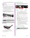
Round-Holed Rack Installation
Before installing the rails onto a unthreaded round-holed
rack, the round-hole rail kit adaptors (Figure 6) must be
installed on the ends of the outer rails.
Figure 6. Round-Holed Rack Adaptors
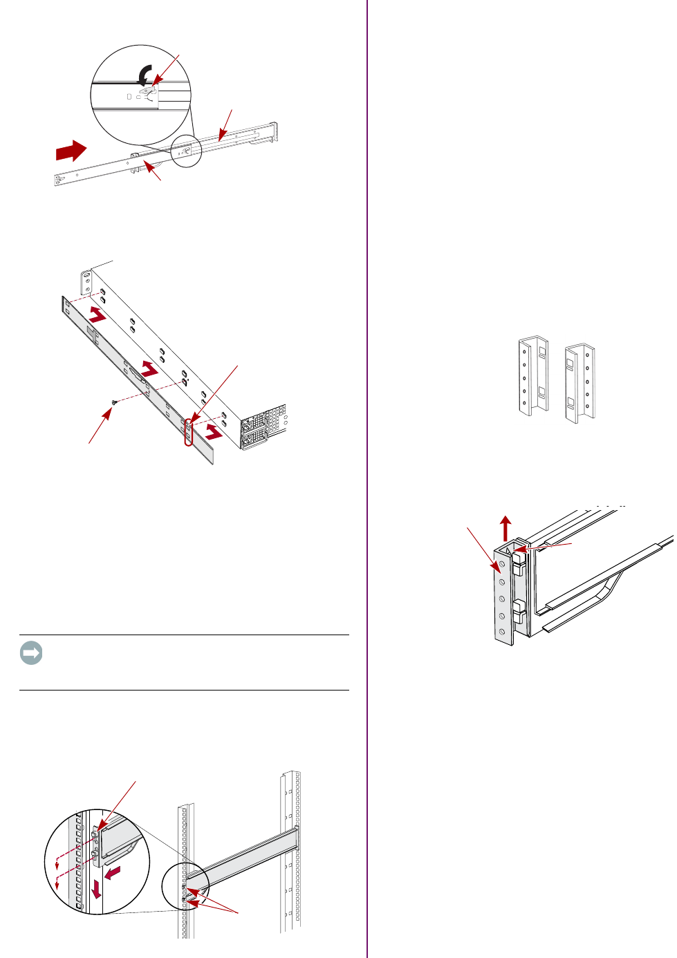
1. Attach the adaptors (Figure 7) to both ends of the
rail:
Figure 7. Attach the Adaptor to the Front
a. Position the adaptor stamped “A” at the front of the
left outer rail (end with the graphic label).
NOTE:
Make sure the stamp is at the top and the square
adaptor holes are aligned with the hooks on the outer rail.
b. Press the adaptor onto the hooks and slide it
upwards until it locks (clicks).
NOTE:
The rail buttons will snap into the square holes.
c. Repeat Steps a–b for the left rear adaptor
(stamped “B”).
2. Facing the rack, position the left rail in the rack,
aligning the adaptor holes with the front left rack
holes being used (Figure 8 on page 3).
Middle Member Latch
Middle Member
Outer Member
Screw
Align Rear
Holes to Tabs
Hooks
Tab
A
B
(Front)
(Rear)
Adaptor
“A” Stamp