14
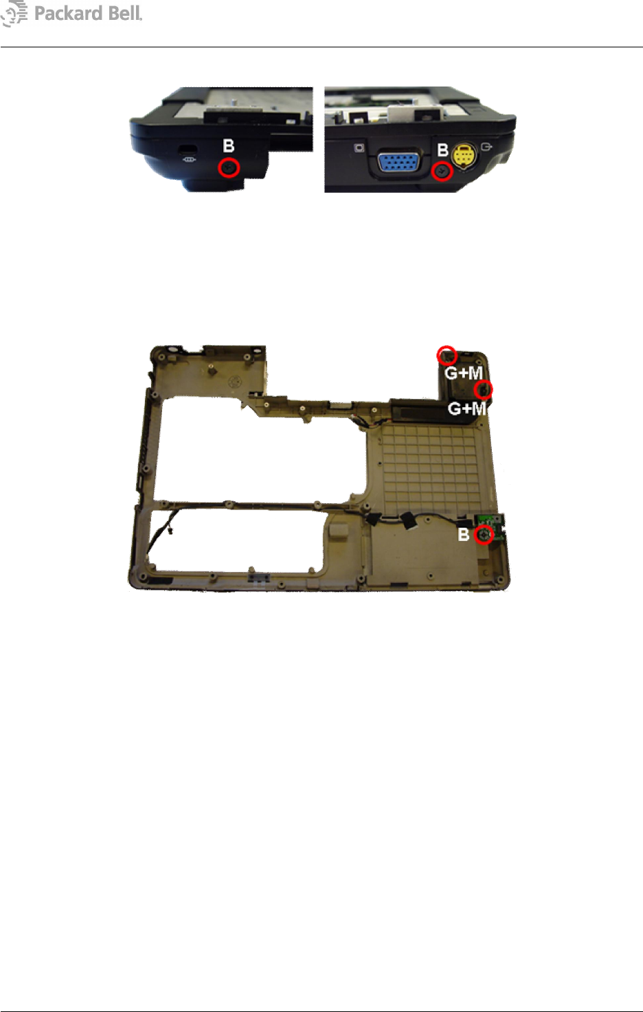
4. Remove the screws from the rear (2xB).
5. Remove bottom cover from base assembly.
6. Disconnect the subwoofer connector.
7. Remove the screws (2xG) and lift out the subwoofer assembly.
8. Remove the rubber stabilizers (2xM) from the subwoofer assembly.
9. Remove the screw (1xB) from the modem connector board.
10. Disconnect the cable connector from the modem connector board.
Main Board Assembly
To remove the main board from the top cover, follow the steps below:
1. Remove the screws (2xO) from the VGA connector on the rear.
2. Disconnect left speaker connector from main board.
3. Remove the screw (1xN).
4. Slightly lift main board and slide out left speaker assembly.
5. Disconnect right speaker from main board.
6. Remove the screw (1xG) and take away the right speaker assembly.
7. Remove the screw (1xB) from main board.
Fig. 24 The screws at the bottom base rear.
Fig. 25 The bottom cover.


