


16
Connections
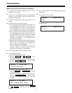
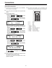
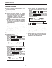
2 Select the connector for input of control signals from
the controller.
Press the key ( i ) to change
the menu setting item.
“Menu-4 Input” appears on the LCD panel.
Select the CONTROL OUT connector to be used
using the ! # keys.
When control is to be performed from a control panel,
select RS-422 and select RS-232C when it is to be
performed from a PC.
STOPSTART
START
2
MENU+
When the settings are completed, press the
key ( i ) once again to exit the menu
settings.
START
2
MENU+
Menuj 4 Input
RSj 232C RSj 422
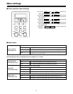
3 Set the CONTROL OUT connector according to the
type of pan-tilt connected and the connection
distance.
Press the key ( i ) to change
the menu setting item.
When “Menu-5 Output-1” appears on the LCD panel,
use the ! # keys and select
RS-232C or RS-422 according to the pan-tilt head
system to be connected.
STOPSTART
START
2
MENU+
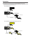
7.
6.
Set the power switch on the pan-tilt head to ON.
8.
Set the POWER switch on the control panel to ON to
control the pan-tilt head system. When an AW-RP505 is
being used as the control panel, select the pan-tilt head
system using the CONTROL button on the control
panel.
9.
When the POWER switch on the control panel is set to
OFF after control of the pan-tilt head is completed, the
power of pan-tilt head system will turn off.
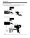
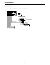
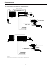
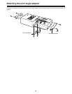
Connection procedure
1.
Connect the AW-PS301 AC adapter to the DC 12V IN
connector on this adapter.
2.
Set the control panel selector switch on this adapter to
B.
5.
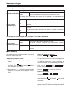
Dial Up Adapter settings
1 Set this adapter to direct mode.
Press the key ( i ) to open
the menu settings.
When “Menu-1 Function” appears on the LCD panel,
use the ! # keys and select
Direct (direct mode).
STOPSTART
START
2
MENU+
Menuj 1 Function
Tx Rx Direct
Menuj 5 Output-1
RSj 232C RSj 422
3.
1 Connect the PAN/TILT CONTROL OUT connector
on the control panel to the PAN/TILT CONTROL IN
connector on this adapter using a 10 BASE-T
(equivalent to UTP category 5) straight cable.
The connection distance can be extended up to 500
meters.
2 Connect the CAMERA CONTROL OUT connector on
the control panel to the CAMERA CONTROL IN
connector on this adapter using a coaxial cable
(equivalent to 5C-2V).
The connection distance can be extended up to 500
meters.
<Note>
This connection is not possible with the AW-RP301
control panel as it is not equipped with a CAMERA
CONTROL OUT connector.
3 When a PC is used as the control panel, connect it to
the TO RCB/PC connector on this adapter.
4.
Set the power switch on this adapter to ON.