


7
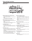
Connections
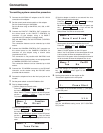
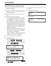
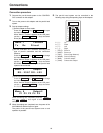
Dial Up Adapter settings
1 Set this adapter to transmit mode.
Press the key ( i ) to open
the menu settings.
When “Menu-1 Function” appears on the LCD panel,
use the ! # keys and select
Tx (transmit mode).
STOPSTART
START
2
MENU+
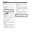
2 Select the telephone line.
Press the key ( i ) to change
the menu setting item.
When “Menu-2 Modulate” appears on the LCD panel,
use the ! # keys and select
Tone or Pulse according to the telephone line to be
used.
STOPSTART
START
2
MENU+
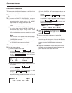
4 Set whether or not to turn the power of the pan-tilt
head system off when the telephone line is cut.
Press the key ( i ) to change
the menu setting item.
“Menu-7 Pw-Off” appears on the LCD panel.
Select “Yes” if the power of the camera/pan-tilt head
is to be turned off when the telephone line is cut.
Select “No” if the power of the camera/pan-tilt head is
not to be turned off when the telephone line is cut.
START
2
MENU+
3 Set this adapter to switch to an external line via a
PBX (private branch exchange).
Press the key ( i ) to change
the menu setting item.
When “Menu-3 PBX” appears on the LCD panel, use
the ! # keys and set the
external line selector number to 0 or 9.
Select “None” if a PBX is not to be used.
STOPSTART
START
2
MENU+
Menuj 1 Function
Tx Rx Direct
Menuj 3 PBX
None 0 and 9 and
Menuj 7 Pw-Off
Yes No
Menuj 2 Modulate
Tone Pulse
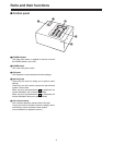
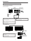
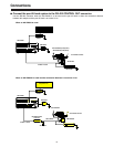
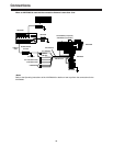
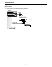
Transmitting system connection procedure
1.
Connect the AW-PS301 AC adapter to the DC 12V IN
connector on this adapter.
2.
Set the control panel selector switch on this adapter.
Set it to A when using an AW-RP605.
Set it to B when using an AW-RP301, 501, 505, or WV-
CB700A.
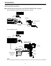
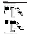
5.
Connect the TO MODEM connector to the RS-232C
connector on the modem using the RS-232C cable
provided with the modem.
6.
Set the power switch on the AW-DU600 to ON.
1: Press Start
1:
jj jj jj
If the modem is not connected correctly, [---] will appear
on the LCD panel.
<Note>
Set the AW-RP605 setting menu (EXT CONTROL
OUT) to ON.
9.
Set the power switch on the modem to ON.
“Press Start” appears on the LCD panel.
7.
Connect the telephone line to the line input jack on the
modem.
8.
3.
Connect the PAN/TILT CONTROL OUT connector on
the control panel to the PAN/TILT CONTROL IN
connector on this adapter using a 10 BASE-T
(equivalent to UTP category 5) straight cable.]
With the AW-RP605, use the EXTERNAL CONTROL
OUT connector.
The connection distance can be extended up to 500
meters.
4.
Connect the CAMERA CONTROL OUT connector on
the control panel to the CAMERA CONTROL IN
connector on this adapter using a coaxial cable
(equivalent to 5C-2V).
This connection is not possible with AW-RP301 and
AW-RP605 control panels as they are not equipped with
a CAMERA CONTROL OUT connector.
The connection distance can be extended up to 500
meters.
When the settings are completed, press the
key ( i ) once again to exit the menu
settings.
START
2
MENU+