


5
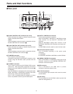
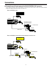
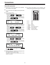
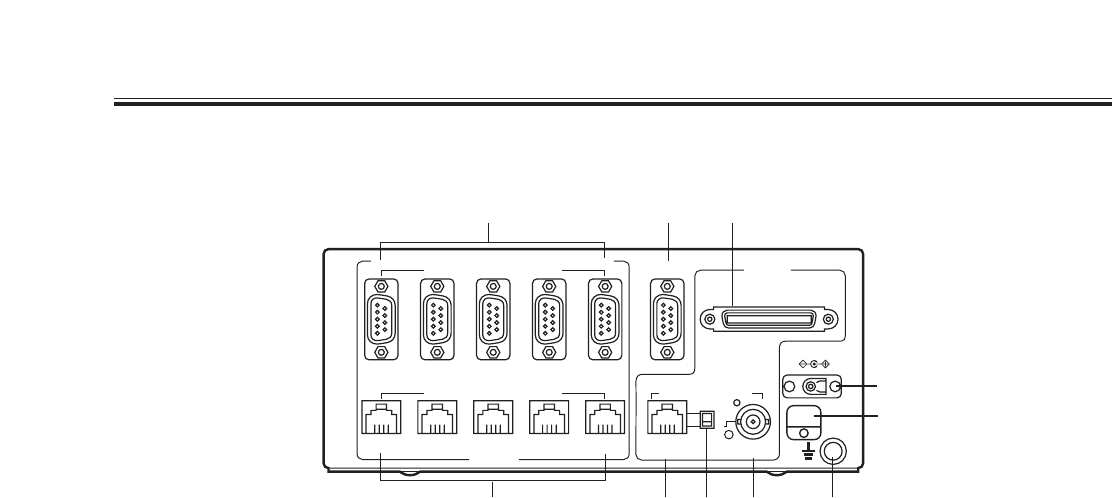
6 RS-232C CONTROL OUT connectors (P1 to P5)
These connectors are used to connect the pan-tilt head
system controlled with RS-232C.
<Note>
These connectors cannot be used in conjunction with the
RS-422 CONTROL OUT connectors 7.
7 RS-422 CONTROL OUT connectors (P1 to P5)
These connectors are used to connect the pan-tilt head
system controlled with RS-422.
<Note>
These connectors cannot be used in conjunction with the
RS-232C CONTROL OUT connectors 6.
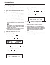
8 TO MODEM connector
This is used to connect the modem.
Connect this connector to the RS-232C connector on the
modem using the RS-232C cable provided with the
modem.
9 TO RCB/PC connector
This is used to connect the WV-CB700A RCB (remote
control box). When the RCB is connected, the control
signals input to the CAMERA CONTROL IN connector <
are disabled.
If the WV-CB700A is connected to the control panel (AW-
RP301, AW-RP501 or AW-RP505), operation of the IRIS
control on the control panel takes precedence.
Also, if a PC is connected when the adapter is in direct
mode, it is possible to control a pan-tilt head system.
: PAN/TILT CONTROL IN connector
This is used to connect the controller.
When an AW-RP301, AW-RP501 or AW-RP505 is being
used, connect it to the PAN/TILT CONTROL OUT
connector.
When an AW-RP605 is being used, connect it to the
EXTERNAL CONTROL OUT connector on the main unit.
<Note>
An AW-RP605 cannot be used for control in direct mode.
; Control panel selector switch
This is switched according to the control panel
connected.
A: AW-RP605
B: AW-RP301,AW-RP501,AW-RP505, and WV-CB700A
< CAMERA CONTROL IN connector
When an AW-RP501 or AW-RP505 is being used as the
controller, connect it to the CAMERA CONTROL OUT
connector on the control panel.
= GND connector
This is connected to the GND earth to prevent
malfunction caused by external noise.
> DC 12V IN connector
This is the power input connector and is used to connect
the AW-PS301.
? Cable clamp
This is provided for the AW-PS301 cable to prevent the
cable from being pulled out.
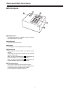
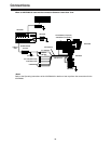
Parts and their functions
$
Rear panel
RS-232C CONTROL OUT
P5 P4 P3 P2 P1
P5 P4 P3 P2 PAN/TILT
CONTROL IN
CAMERA
CONTROL IN
GND
DC 12V IN
TO RCB/PC
A
B
P1
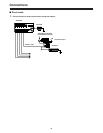
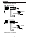
TO CAMERA & PAN/TILT HEAD TO MODEM
RS-422 CONTROL OUT
TO CAMERA & PAN/TILT HEAD
TO CONTROL PANEL
6
89
7
:; <
OUT PUT
INPUT
=
>
?