


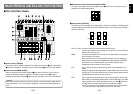
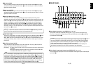
tMix Switch [MIX]
Press it to switch the signal selected with A-Bus Input Selection Switch } to the signal
selected with B-Bus Input Selection Switch q or vice versa by the mix effect. The switch
lights when MIX is selected.
yWipe Switch [WIPE]
Press it to switch the signal selected with A-Bus Input Selection Switch } to the signal
selected with B-Bus Input Selection Switch q or vice versa by the wipe effect. The switch
lights when WIPE is selected.
uAuto Take Switch [AUTO TAKE]
This switch is used for automatically wiping or mixing instead of performing these
operations manually using the Fader Lever i. This switch becomes operational when the
Fader Lever i is set all the way toward the A or B side, and when it is pressed once, the
wipe or mix operation is performed automatically. The transition time for switching the
signals can be adjusted using the AUTO TAKE U control. While the signals are being
switched, the AUTO TAKE switch lights, and it goes off when the signals are switched
completely. During an auto take operation, no manual operations will be performed even if
the Fader Lever i is moved.
iFader Lever [A/B]
This lever is used to switch the signal selected with A-Bus Input Selection Switch } to the
signal selected with B-Bus Input Selection Switch q or vice versa by the wipe or mix
effect. When the lever is moved from A to B, the video signal is also switched from A to B
accordingly. Similarly, when the lever is moved from B to A, the video signal is switched
from B to A.
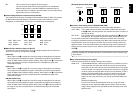
oBus Tally Indicators [A], [B]
These indicate the output statuses of the A-bus and B-bus. The [A] or [B] LED lights to
indicate that A-bus or B-bus signals are being output.
[Examples] • [A] lights when the Fader Lever is at the A side since only the A-bus signals
are output.
• Both [A] and [B] light when the Fader Lever is between the A and B sides
since both A-bus and B-bus signals are output.
15 (E)
ENGLISH
BBOUT
GLIN
/BBOUT
PVW
OUT
TALLY & INCOM
PGM OUT
2
54
DC 12V IN
SET UP
USB
EXT
TAKE
PGM
Y / C
OUT
1342
GND
321
1 1
75Ω
AUTO
2345
1234
5
VIDEO
IN
OUT
Y / C IN
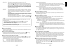
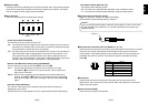
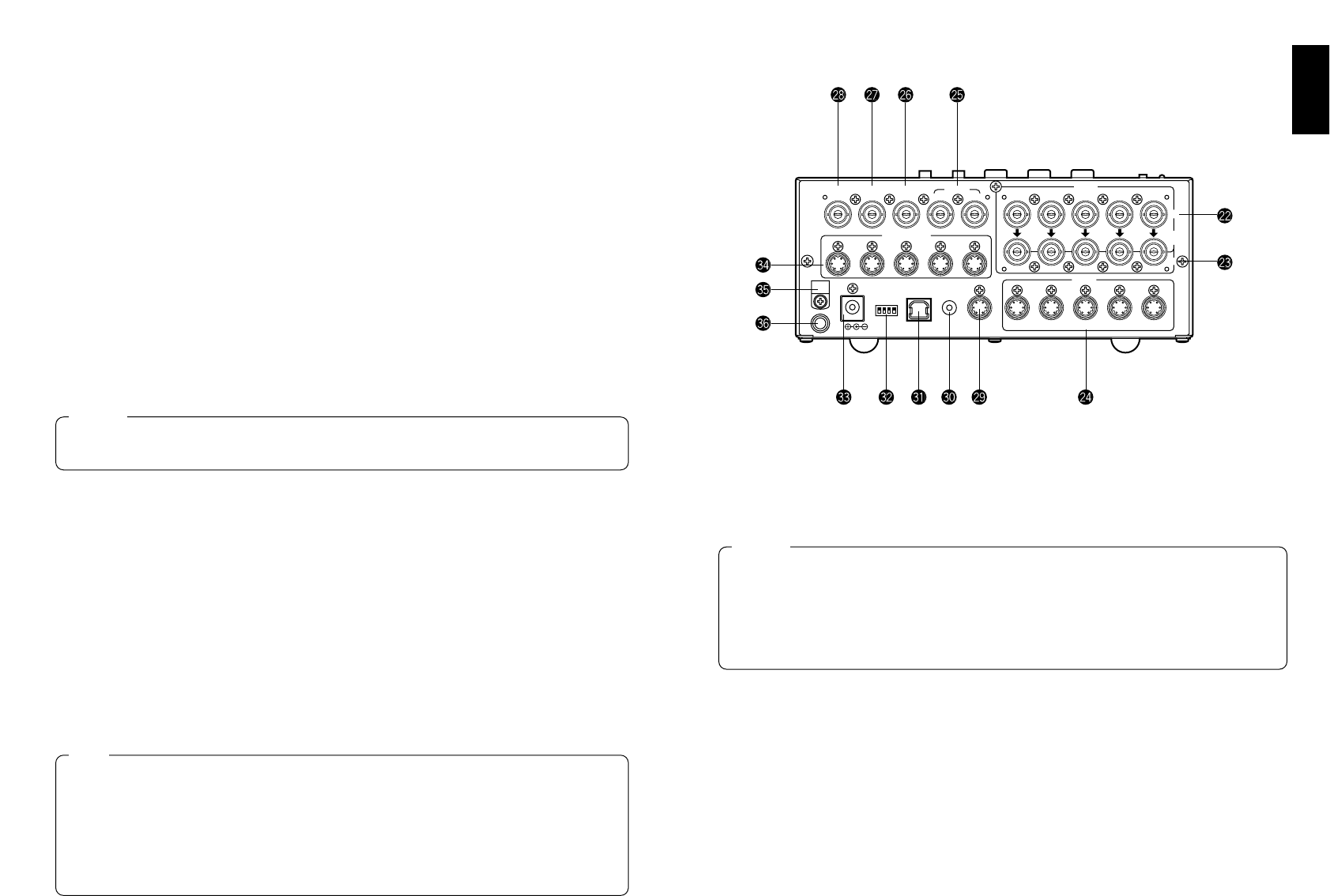
■REAR PANEL
pVideo Signal Input Jacks 1 to 5 [VIDEO IN 1, 2, 3, 4, 5]
These jacks are to input composite video signals. (1 Vp-p, 75-ohm auto-terminated)
There are 5 input jacks corresponding to A-Bus Input Selection Switches } and B-Bus
Input Selection Switches q.
[Video Signal Loopthrough Output Jacks [VIDEO OUT 1, 2, 3, 4, 5]
These loopthrough output jacks are for the composite video signals input to Video Signal
Input Jacks p.
14 (E)
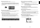
Bus control based on the flip-flop system is enabled by changing the setting of the bus
selector switch [BUS A/B /F.F.]R which is one of the Setup Switches K. Under the flip-
flop system, the signals selected by the A-Bus Input Selection Switches } are always
selected as the programme (PGM) video signals, and the signals selected by the B-Bus
Input Selection Switches q are always selected as the preview (PVW) video signals.
Furthermore, the PGM signals can be replaced with the PVW signals or vice versa by
means of bus switching using the AUTO TAKE Switch u and Fader Lever i.
Note
In using the Auto Take function, be sure to move Fader Lever i all the way to A or B.
Auto Take will not work unless the lever is fully moved to A or B.
Caution
If a BNC coaxial cable is connected to Video Signal Loopthrough Output Jack [, the
75-ohm termination is automatically released. Do not connect a BNC coaxial cable to
any of these jacks in case of connecting YC signals to Y/C Signal Input Jack ]. Use
either composite signals or YC signals as video input signals.
Furthermore, when unstable video signals from a VHS format VTR, DVD player or
other device have been input, the frame synchronizer may malfunction.
Caution