30
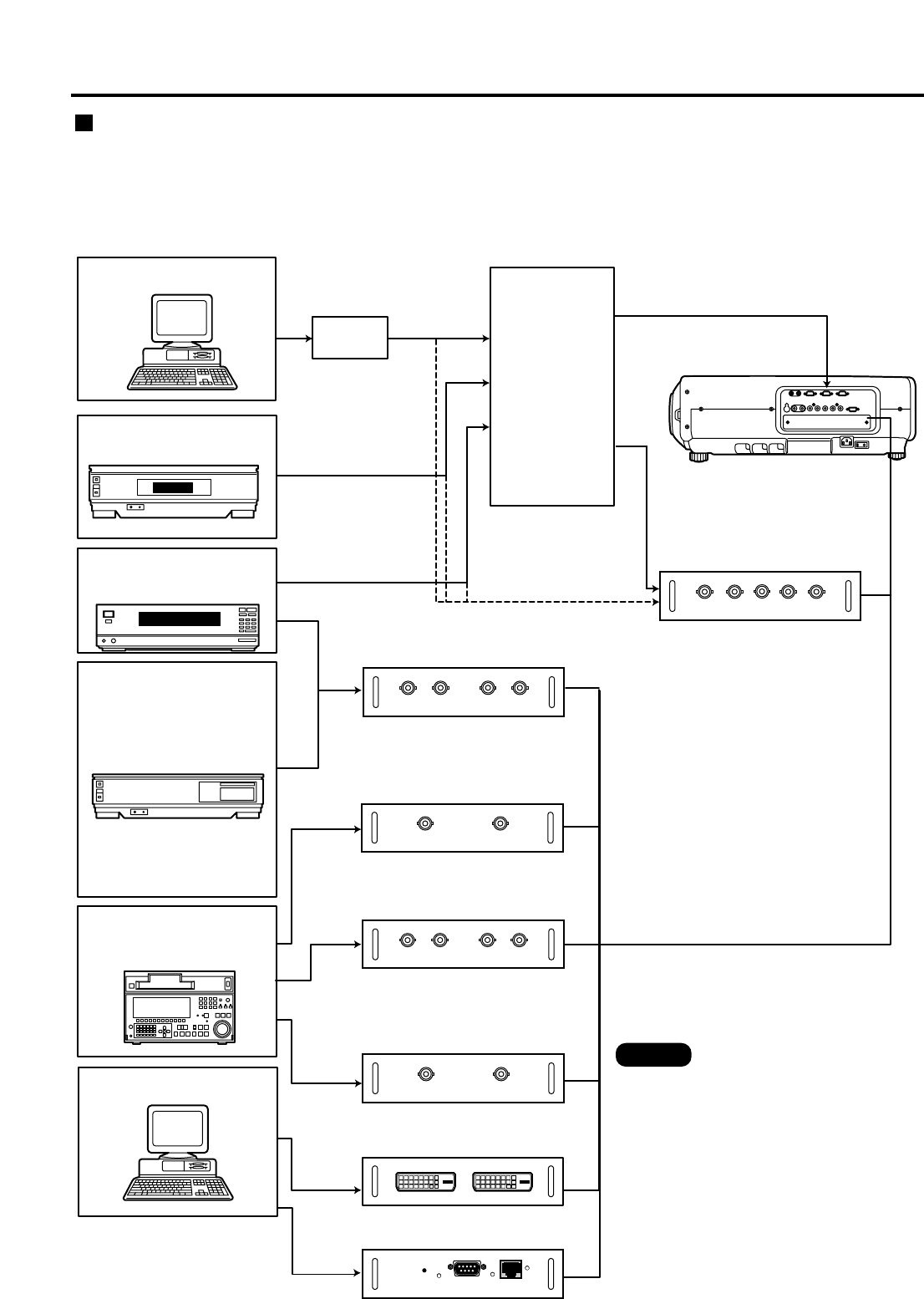
When installing the projector, it is necessary to connect signals to the input module in accordance with the
connecting equipment.
Refer to the following diagram to establish proper signal connection.
• When switching multiple signals of the
same type and connecting to the same
input module (for example, when using
a signal chosen from multiple high-
vision signals), use a signal selector for
this purpose and connect it with the
projector through RS-232C. Those
signals can be used individually
according to the input terminal on the
signal selector.
• Digital signals cannot be connected to
the signal selector.
RGB signal input module
ET-MD95RGB
I/F
Input
Input
Input
Output
RS-232C
Output
RGB signal
Component signal
Video signal input
module ET-MD95VM2
Serial digital input
module ET-MD95SD1
Component signal
SD signal
Projector
RS-232C
input terminal
Signal selector
High-vision video deck
Video deck
(TBC built-in)
Business
digital VCR
PC
Serial digital input
module ET-MD95SD2
DVD player /
BS digital HD tuner
HD serial digital input
module ET-MD95SD3
DVI input module
ET-MD75DV
SD signal
SD signal
DVI
signal
PC
Network module
ET-MD75NT
LAN
Connecting signals to the input module
Note
Installation of input module (optional)


