


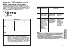
ENGLISH-65
Others
64-ENGLISH
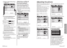
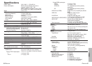
Control commands
The commands which the personal computer can use to control the projector
are shown in the following table.
Command
Control
Contents
Remarks
In standby mode, all commands other than
the PON command are ignored.
BThe PON command is ignored during
lamp ON control.
BIf a PON command is received while the
cooling fan is operating after the lamp
has switched off, the lamp is not turned
back on again straight away, in order to
protect the lamp.
Power ONPON
Power OFFPOF
VolumeAVL
Parameter
000–063(Adjustment value 0–63)
Input signal
selection
IIS
Parameter
VID=VIDEO SVD=S-VIDEO
RG1=RGB1(YP
BPR1) RG2=RGB2(YPBPR2)
NWP=NETWORK SDC=SDCARD
Lamp ON
condition query
Q$S
Parameter
0 = Standby
1 = Lamp ON control active
2 = Lamp ON
3 = Lamp OFF control active
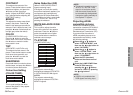
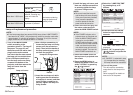
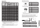
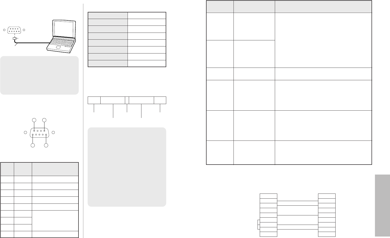
Cable specifications
(When connected to a personal computer)
1
2
3
4
5
6
7
8
9
1
2
3
4
5
6
7
8
9
NC
NC
NC
NCNC
NC
NC
NC
At the projector
At the computer
(DTE specifications)
Using the SERIAL connector
The serial connector which is on the side connector panel of the projector
conforms to the RS-232C interface specification, so that the projector can be
controlled by a personal computer which is connected to this connector.
Connection
Basic format
The data sent from the computer to
the projector is transmitted in the
format shown below.
Communications settings
Signal level RS-232C
AsynchronousSync. method
Baud rate
Parity
9 600 bps
None
Character length 8 bits
Stop bit 1 bit
X parameter None
S parameter None
STX Command : Parameter ETX
Start byte
(02h)
3 bytes
1 byte
1 byte–5 bytes
End byte
(03h)
NOTE:
BIf sending multiple commands,
check that a response has been
received from the projector for
one command before sending
the next command.
BWhen a command which does
not require parameters is sent,
the colon (:) is not required.
B
If an incorrect command is sent from
the personal computer, the “ER401”
command will be sent from the
projector to the personal computer.
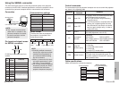
NOTE:
BUse a proper communication
cable which is suitable for the
personal computer to connect
the serial connector and the
personal computer.
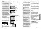
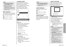
D-Sub9p (male)
Communication cable
SERIAL(female)
Computer
1
5
6
9
D-SUB 9-pin connector seen from
outside
Pin
No.
Signal
name
Contents
#
NC
$
TXD Transmitted data
%
RXD Received data
&
NC
'
GND
(
DSR
)
CTS
Connected internally
*
RTS
NC
+
Pin layout and signal names
for SERIAL connector
OSH Shutter function
Operation will be switched between ON and
OFF each time the command is sent. Do
not switch operation ON and OFF after only
short periods of time.