


Cable
6
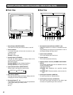
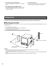
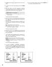
The connections described below should be made by qualified service personnel or system installers.
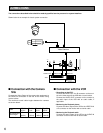
Shown below is an example of a basic system connection.
CONNECTIONS
Video Switcher
AUDIO OUT VIDEO OUT VIDEO IN
VCR
OUT
G
FOCUS
OUT
VIDEO
OUT AC IN
B
IN
A
IN
STANDBY
ON
STANDBY
OFF
AUDIO
IN
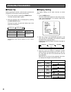
Recommended
cable length
RG-59/U
3C-2V
RG-6/U
5C-2V
RG-11/U
7C-2V
RG-15/U
10C-2V
250 m
(825 ft)
500 m
(1 650 ft)
600 m
(1 980 ft)
800 m
(2 640 ft)
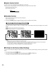
■ Connection with the Camera
Site
Connect the Video Output of the camera site equipment to
the VIDEO IN connectors on the rear of the monitor using
coaxial cables.
The maximum coaxial cable lengths between the cameras
are shown below.
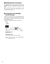
■ Connection with the VCR
• Recording on the VCR
Connect the VIDEO OUT A or B connector on the moni-
tor to the video input of the VCR with a coaxial cable.
Connect the AUDIO OUT connector on the monitor to
the audio input of the VCR with an audio cable, if
applicable.
• Monitoring the Playback picture
Connect the video output of the VCR to the VIDEO IN A
or B connector on the monitor with a coaxial cable.
• Monitoring the Playback audio
Connect the audio output of the VCR to the AUDIO IN
connector on the monitor with an audio cable.