


PANDUIT® DPoE™ Power Patch Panel User’s Guide Issue 2.2
Part Number: PN378A
11
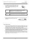
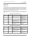
From
Network
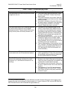
Grounding Requirements
Network Connection
5. If the Element Manager is not being used to
remotely manage the network of DPoE™
Power Patch Panels, skip to Connecting the
Powered Devices below. Otherwise, using a
standard patch cord (for example, PANDUIT
part number UTPCH3 or UTPSP3), connect
the IN management port on the back of the
panel to an Ethernet switch. A DHCP Server
must be on this network (unless the DPoE™
Power Patch Panel has been configured for
Static IP operation). The panel may also be
directly connect to a PC with the PANDUIT
Element Manager installed, but this PC must
be setup as a DHCP Server.”
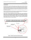
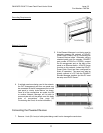
6. If multiple panels are being used in the network,
the OUT management port from one panel may
be connected to the IN management port on the
next panel in a daisy chain fashion, as shown.
Once all of the connections are made, the EM
or another Network Manager will be able to
communicate with all the panels over this daisy
chain of connections. (See page 29,
Provisioning the Panel, for more information.)
Connecting the Powered Devices
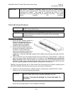
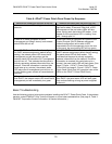
7. Remove 1 inch (25.4 mm) of cable jacket being careful not to damage the conductors.