


PANDUIT® DPoE™ Power Patch Panel User’s Guide Issue 2.2
Part Number: PN378A
57
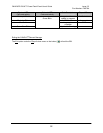
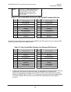
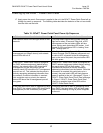
Table 17: Color-Coded Wire Positions for 802.3af-2003 Compliant Devices
Pin
Outs
EIA/TIA 568A
Pin
Outs
EIA/TIA 568B
5 WHITE/BLUE 5 WHITE/BLUE
4 BLUE 4 BLUE
1 WHITE/GREEN 1 WHITE/ORANGE
2 GREEN 2 ORANGE
3 WHITE/ORANGE 3 WHITE/GREEN
6 ORANGE 6 GREEN
7 WHITE/BROWN 7 WHITE/BROWN
8 BROWN 8 BROWN
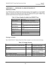
The DPoE™ Power Patch panel supports standard IEEE 802.3af-2003 devices as well as alternate PoE
devices consistent with the Cisco legacy devices.
Table 18: Color-Coded Wire Positions for Alternate PoE Devices
Pin
Outs EIA/TIA 568A
Pin
Outs EIA/TIA 568B
5 WHITE/BROWN 5 WHITE/BROWN
4 BROWN 4 BROWN
1 WHITE/GREEN 1 WHITE/ORANGE
2 GREEN 2 ORANGE
3 WHITE/ORANGE 3 WHITE/GREEN
6 ORANGE 6 GREEN
7 WHITE/BLUE 7 WHITE/BLUE
8 BLUE 8 BLUE
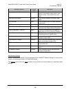
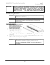
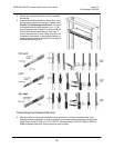
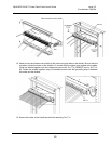
7. For best performance, the cable pair twists should be maintained as close as possible to the point
of termination. Punchdown the conductors with a 110 Punchdown tool (
PANDUIT part
no.PDT110). Record port information on the
PANDUIT DPoE™ Power Patch Panel Installation
Worksheet (
PANDUIT part no. PN377*). To ensure proper shielding, there must be approximately
1" (25.4 mm) between the cable foil or braid covered with copper tape and the punchdown
connector.
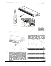
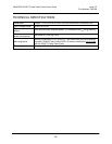
NOTE:
The DPoE™ Power Patch Panel can
terminate most 22-24 AWG solid or
stranded IWC wire with a .050”
(1.27mm) max o.d. either PVC or
Plenum rated.